A meteorological radar
system locates
precipitation such as rain,
snow or hail, measures their intensity, and possibly identifies hazardous phenomena.
Lightning, hail, and strong wind shears in the cloud are added to the risk of
icing up and can endanger the flight if the
pilot attempts to fly through.
The
pitch,
yaw and roll angles of an aircraft vary all the time, which greatly complicates the logic of scanning in
azimuth and in elevation of the meteorological volume in front of the aircraft.
This solution represents a particularly severe penalty in the case of a multimode radar
system.
Note that multimode scanning of the meteorological field requires a beam agility that is difficult to obtain mechanically because of the mechanical
inertia of the antenna, which necessitates high motor torques, which severely tests the motors and therefore the reliability of the system.
This implies overspecification of the entire system, representing a penalty as much in terms of weight as in terms of electrical
power consumption and finally of cost.
Based on a purely mechanical solution with two rotation axes, the
inertia of the antenna can be compensated only by overspecifying the motors, which represents a penalty in the context of an airborne application.
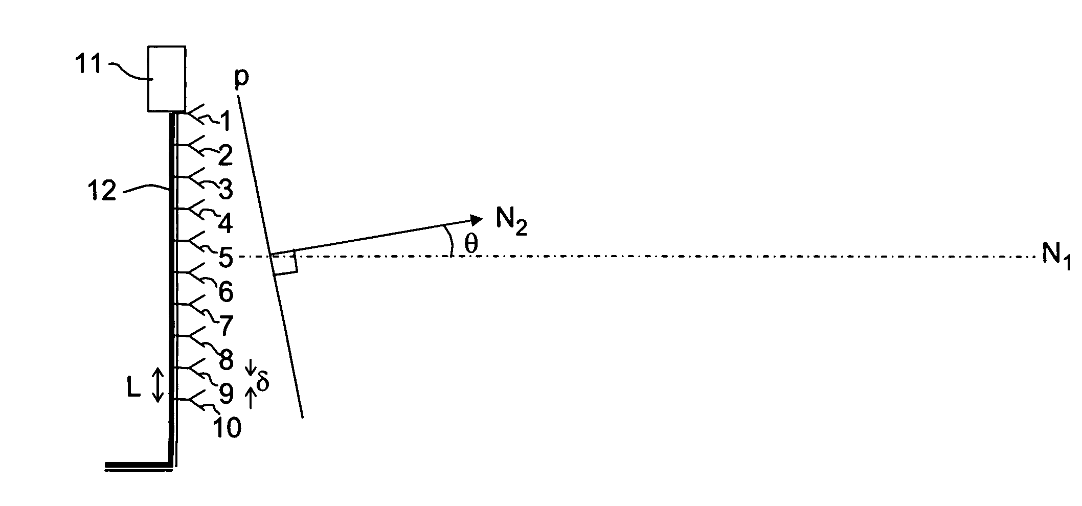
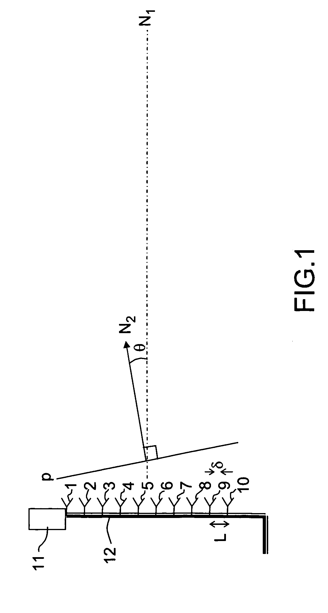
Consequently, for a given
azimuth, there is a significant
delay between measurements for the upper portion of the meteorological volume and measurements for the lower portion.
As a result the measurements in a
vertical slice are hardly contemporaneous, which induces an inaccuracy term into the vertical
processing of the signals.
One solution that could be envisaged would be to have the
antenna effect mechanical scanning, but the inevitable conclusion is that, because of the small vertical extent of the field, the frequency of the antenna turnaround phases would impose a heavy penalty on the efficiency of the radar system, i.e. the ratio between the time
usable by the radar function and the overall time.
However, most such antennas have a large overall size and are not well suited to onboard applications.
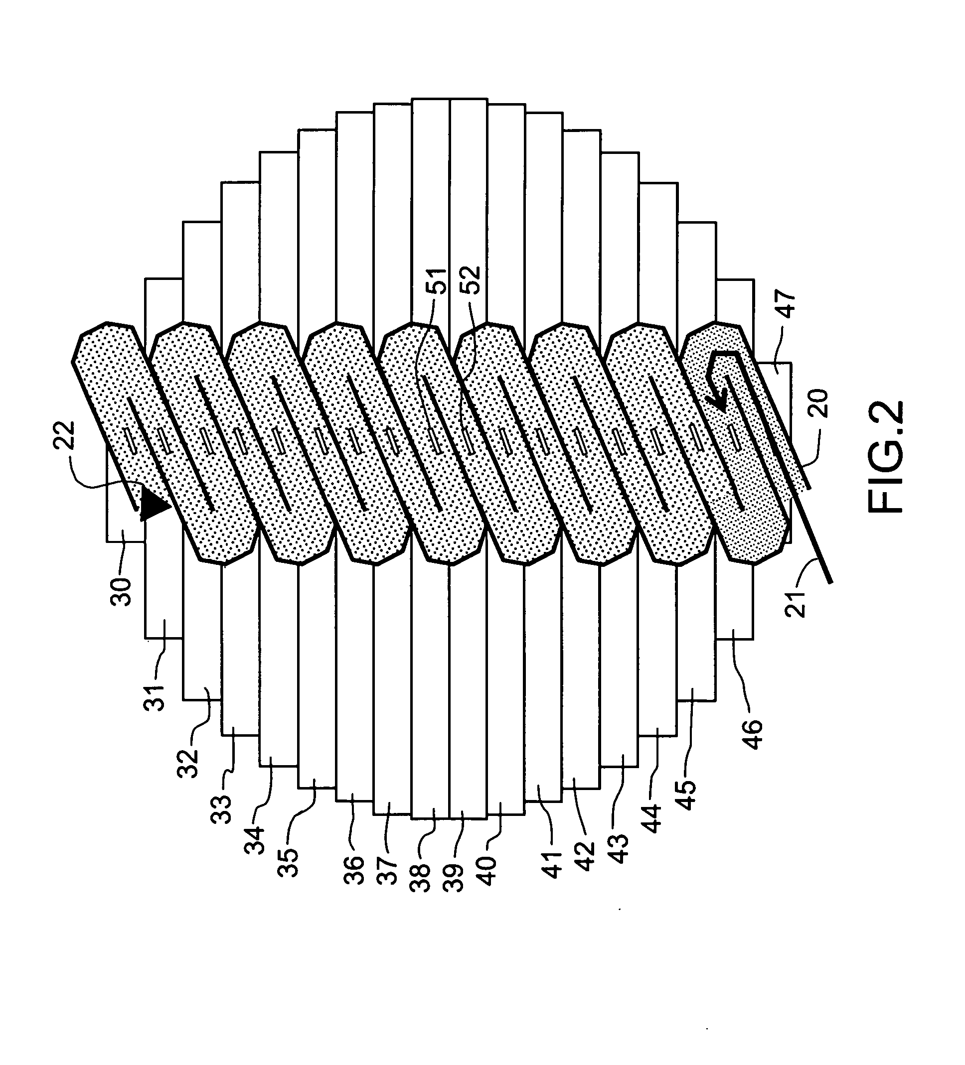
However, this latter solution notably has the drawback of using oblique waveguides, on the front face and on the rear face.
Such waveguides, the complex wave paths whereof include many diversions, can be difficult to fabricate.
This impacts on the cost of the antenna, which can become prohibitive, notably in the case of a civil application such as a meteorological radar system.
Used more particularly in military applications, such solutions are not well suited to meteorological
radar systems.
Apart from the fact that
power consumption would be very high, the large number of phase-shifters or the use of phase-shifters with a large number of bits would make the cost of the antenna prohibitive.
Moreover, the reliability of an electronic scanning antenna using
microwave phase-shifters continues to be more difficult to guarantee than that of a mechanical antenna, as secondary and diffuse lobe performance can deteriorate rapidly with failures of phase-shifters or their control circuits.

