Temperature adjustable airflow device

Inactive Publication Date: 2010-06-10
GRAND RAM +1
View PDF1 Cites 10 Cited by
  • Summary
  • Abstract
  • Description
  • Claims
  • Application Information

AI Technical Summary

Benefits of technology

[0014]It is another object of the invention to provide a temperature adjustable airflow device that is simple construction and economical to the manufactures.
[0015]It is still another object of the invention to provide a temperature adjustable airflow device that utilizes a vortex tube and is easy and safe to use to adjust the temperature of the gas output of the device.
[0016]It is still another object of the

Problems solved by technology

While vortex tubes are not an efficient as traditional air-conditioning equipment, they are commonly used for inexpensive sport cooling, when compressed air is available.
However, because the air exiting this tube can be hot, this is a disadvantage and make cause injury to a user.
Also, while such and adjustment at the hot end of the tube may raise the temperature of the gas at the cooled end of the tube, it is not always practical to use this approach to increase the pressure of the cold air exiting the tube.
As indicated, while has been conventional in the prior art to control the temperature of the discharged cold stream by providing a valve at the hot discharge end of the vortex tube, not only is such placement of a valve at the hot end of the tube inconvenient and potentially dangerous to the user wh

Method used


Image

  • Temperature adjustable airflow device
  • Temperature adjustable airflow device
  • Temperature adjustable airflow device

Examples


Example

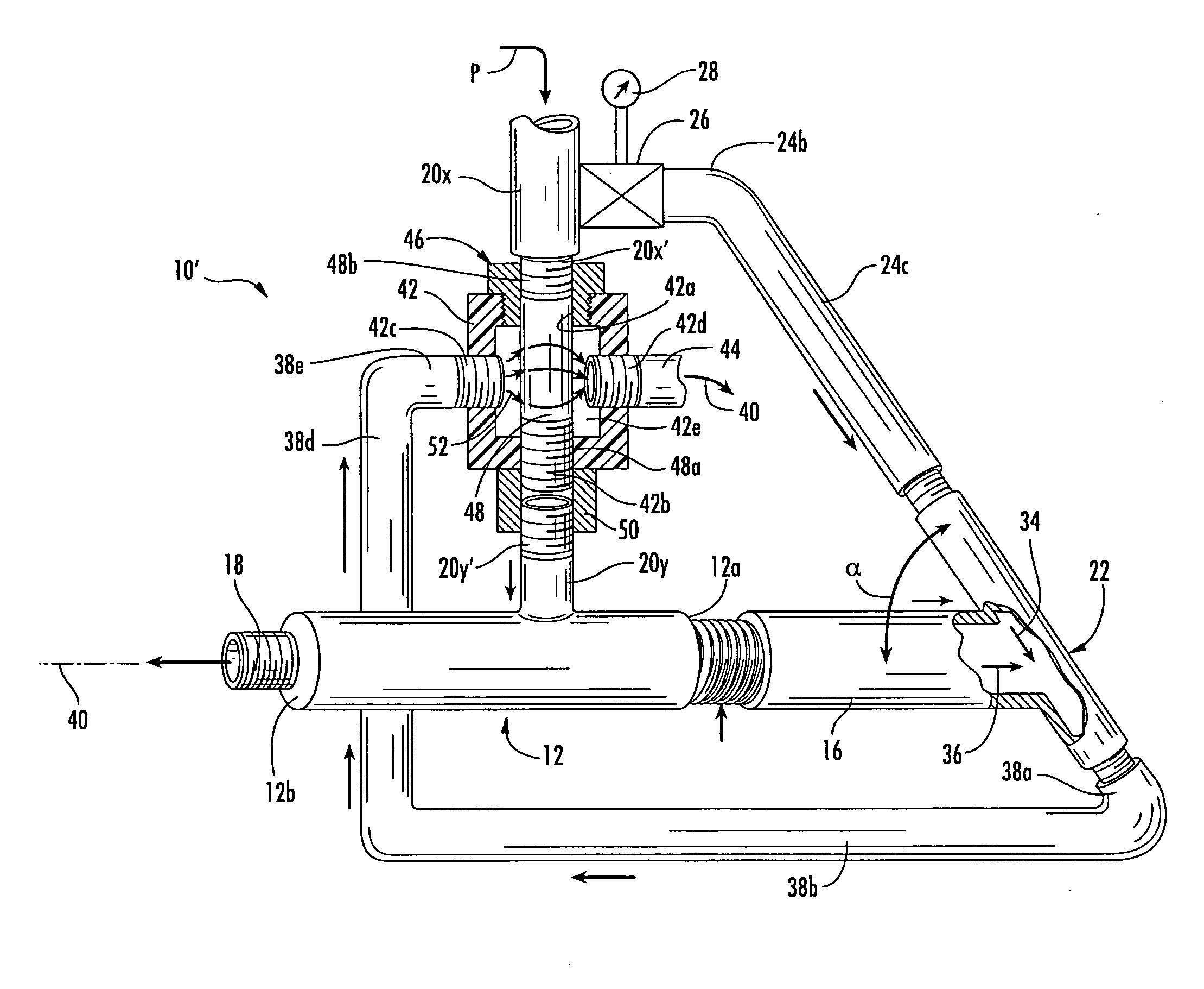
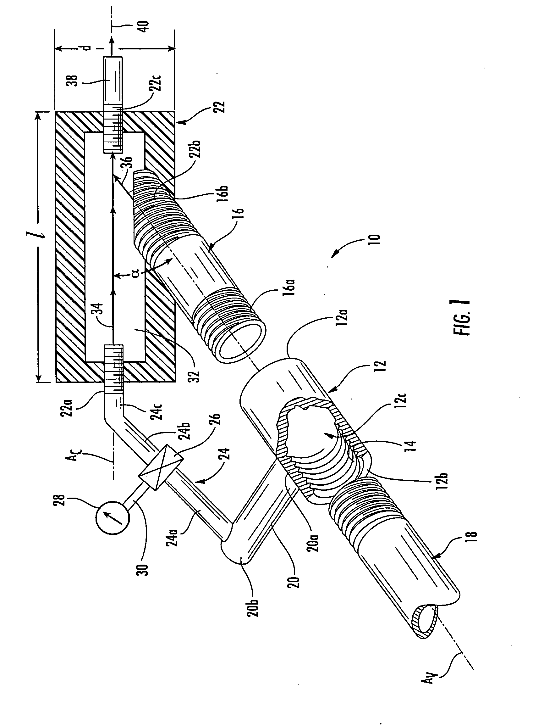
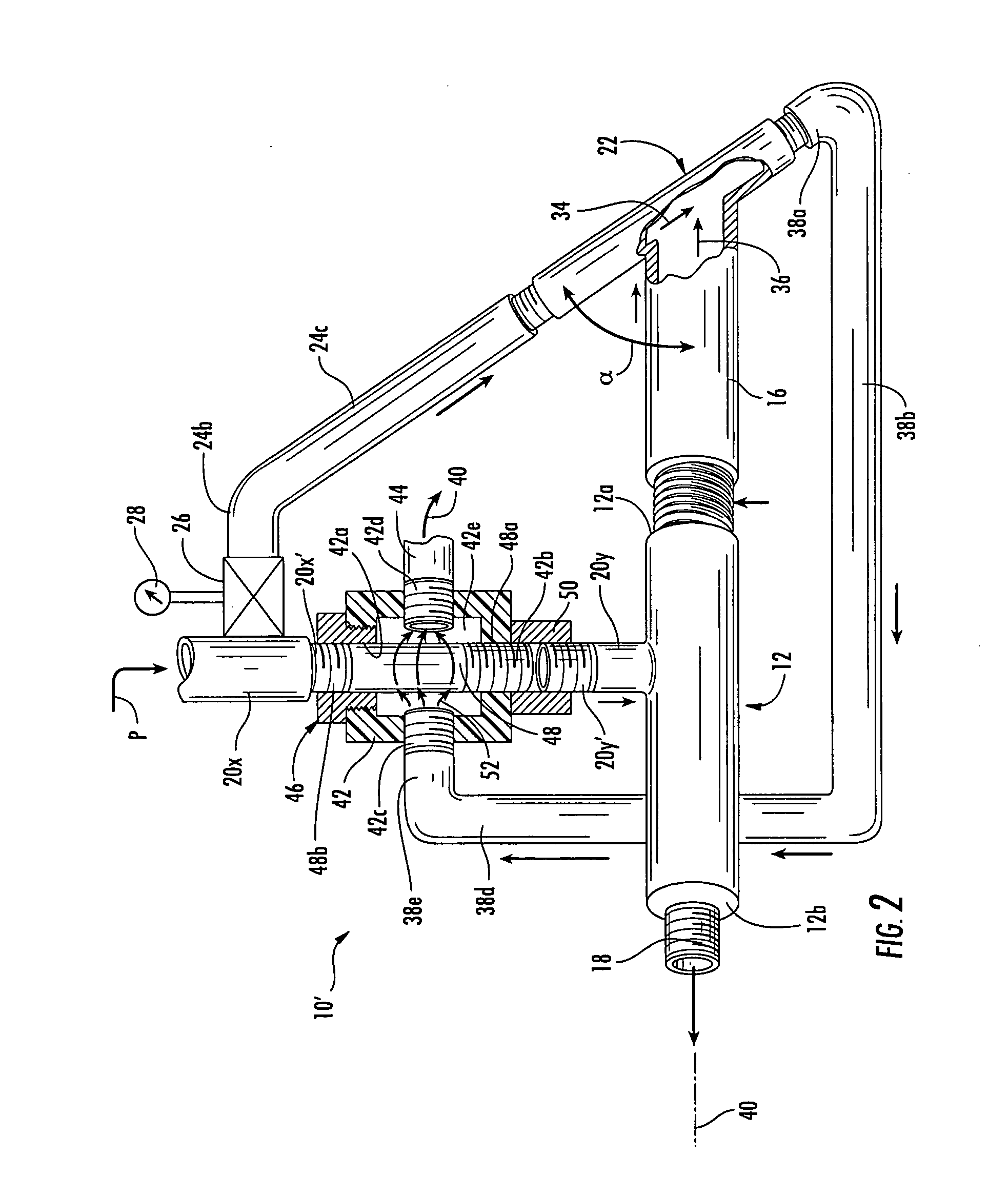
[0027]Referring specifically to the single Figure, a temperature adjustable airflow device in accordance with the invention is generally designated by the reference numeral 10.

[0028]The device 10 includes a vortex tube 12 having a cold end outlet 12a, a hot end outlet 12b, and a spiral chamber 12c. The internal construction of the vortex tube is conventional and the details need not to be described. All of the patents that mentioned in the background of the invention are incorporated herein for the teachings of the details of the vortex tubes, and any such construction can be used. The specific construction or details of the vortex tube are not critical and the subject invention may be used with any conventional or modified vortex tube of the type well known to those skilled in the art.

[0029]The vortex tube 12 has at each of the ends 12a and 12b internal threads 14. A cold air pipe 16 is provided with an external tread 16a at one end and an external tread 16b at the other end, the e...


PUM


Abstract

A temperature adjustable airflow device includes a vortex tube having a high pressure gas inlet and cooled and heated outlets. A mixing chamber is provided having first and second ends, one gas inlet end at the first end and a gas outlet end at the second end, and an intermediate gas inlet end between the first and second ends. A high pressure inlet conduit is connected to the high pressure gas inlet of the vortex tube and to the gas inlet of the mixing chamber. The cooled or the heated vortex tube outlet is connected to the intermediate gas inlet end, the mixing chamber mixing high pressure gas with cooled or heated gas, respectively, from the vortex tube to enhance the pressure of the cooled or heated gas emanating from the vortex tube. The arrangement allows cooled or heated gas from the vortex tube to be output for a given application at a higher pressure that would normally be available.

Description

BACKGROUND OF THE INVENTION[0001]1. Field of the Invention[0002]This invention generally relates to vortex tubes and, more specifically, to a modified temperature adjustable airflow device.[0003]2. Description of the Prior Art[0004]Vortex tubes, known since the 1930s, are mechanical devices that convert gas tinder pressure into hot and cold gas streams. It has no moving parts.[0005]Generally, a typical vortex tube has two openings, one at each end and an intermediate inlet tube for introducing gas under a high pressure into a spiral flow path. While there are different explanations for the way in which vortex tubes work, it is known that when a gas is introduced under high pressure, it is separated into two different streams, a first gas stream exiting one end of the tube being heated air while the gas stream exiting the other end is cooled air. The gases that exit at two opposing ends of the tube being heated and cooled gas streams, are at lower pressures that the pressure of the i...

Claims


Application Information

Patent Timeline
IPC IPC(8): F25B9/02
CPCF25B9/04
Inventor GRAND, RAMGRAND, ELLA A.
Owner GRAND RAM
Why Eureka
Try Eureka