Electronic fence system

a technology of electronic fences and fence posts, applied in the field of electronic fences, can solve the problems of inability to control the animal, prior art methods that have such problems, and the possibility of electronic shock, and achieve the effects of reducing the risk of missing an object, easy finding of lost objects, and convenient installation

Inactive Publication Date: 2010-06-10
DTSYST
View PDF15 Cites 73 Cited by
  • Summary
  • Abstract
  • Description
  • Claims
  • Application Information

AI Technical Summary

Benefits of technology

[0032]Therefore, the present invention can eliminate a risk that an object is missing and easily find a lost object through position tracking.
[0033]Also, the present invention can be installed more easily than a conventio...

Problems solved by technology

Also, when a pet animal (dogs and the like) departs from the fence and comes back there, an electronic shock may be occurred.
However, these prior art methods have such problems as described below:
That is, when an object departs from a limited region drastically, it is impossible to control the animal.
As a result, there comes an uncontrollable state.
Also, electric wires should be laid over wide regions, then it consumes much time and cost.
However, when a laid spot is exposed to an animal, the wires can be easily broken.
Also, communications between a master and a plurality of collars is uniformly...

Method used


Image

  • Electronic fence system
  • Electronic fence system
  • Electronic fence system

Examples


Embodiment Construction

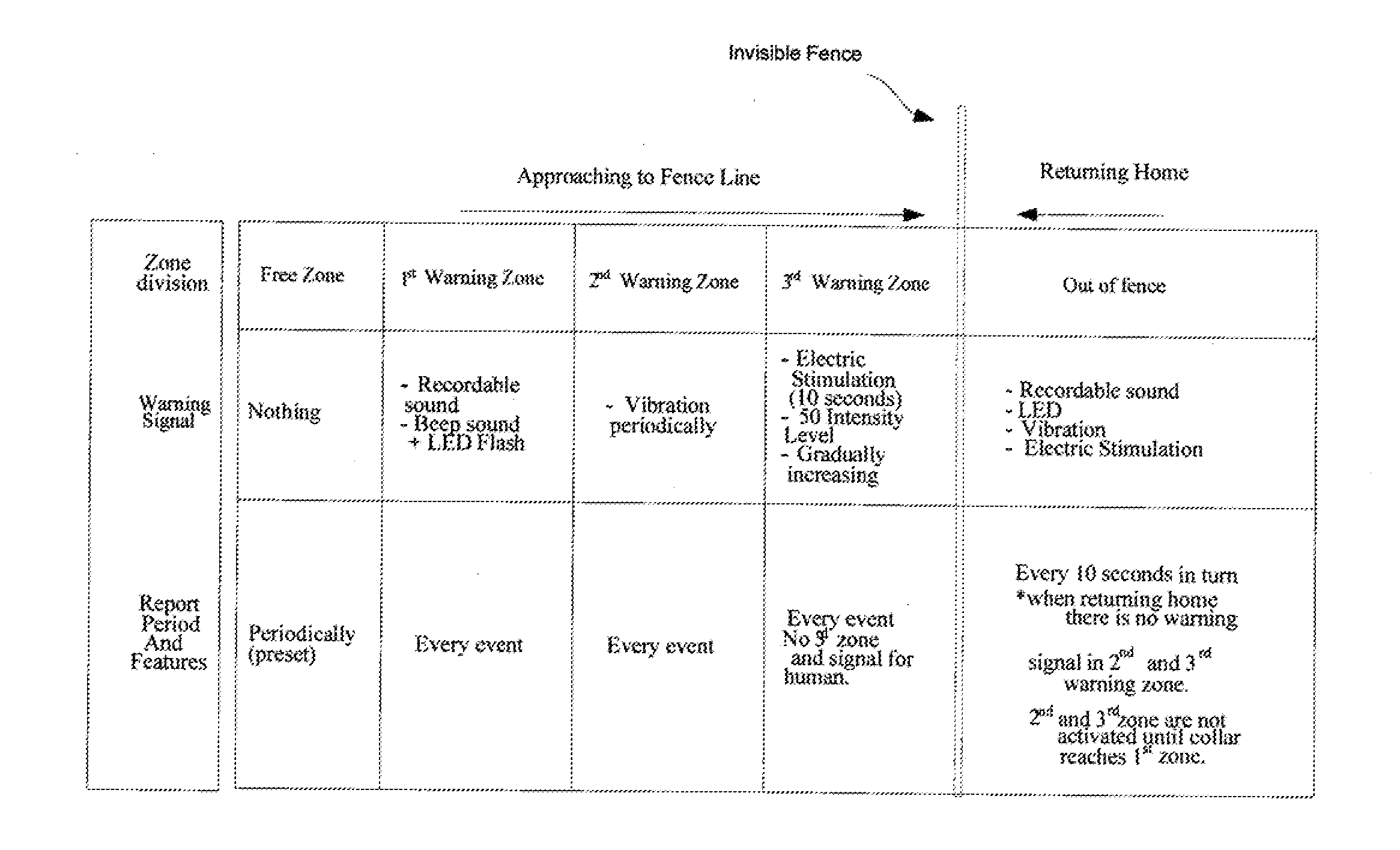
[0111]Hereinafter, exemplary embodiments of an electronic fence system using a GPS according to the present invention will be described with reference to the accompanying drawings. Further, in the following description of the present invention, a detailed description of known functions and configurations incorporated herein will be omitted when it may make the subject matter of the present invention rather unclear. Furthermore, the following terms are defined in consideration of their functions in the present invention, but they can be varied according to intentions of a user and / or an operator or a judicial precedent, and therefore the meaning of each term must be read based on the entire contents of the present specification.

[0112]Particularly, the present invention can act as a guide which monitors activities of an object through using radio communication and restricts the same within a certain range of area via data communication in order to return the animal to the limited area...


PUM


Abstract

An electronic fence system capable of guiding animals under training to return to a predetermined restricted area is disclosed. The fence system may utilize either a plurality of loops to determine direction of travel for a receiver unit or, alternatively, a GPS system. For embodiments utilizing the GPS system, electronic fences are defined in relation to GPS location information. A lock-down mode is used to contain an animal to a very constricted area when a control command is received to initialize the lock down mode or upon a specified condition. Specified conditions include the animal approaching or entering a specified area or, alternatively, a threshold level of charge being reached for a battery that provides power for the receiver unit.

Description

CROSS-REFERENCE TO RELATED APPLICATIONS[0001]The present U.S. Utility patent application claims priority to Korean Patent Application Serial No. 1-1-2008-0764623-11 filed Nov. 4, 2008 under 35 U.S.C. §119 which is incorporated herein by reference in its entirety for all purposes.[0002]The present U.S. Utility patent application also claims priority pursuant to 35 U.S.C. §119(e) to U.S. Provisional Application Ser. No. 61 / 145,066, entitled “Electronic Fence System,” (Attorney Docket No. DT012), filed Jan. 15, 2009, pending which is hereby incorporated herein by reference in its entirety and made part of the present U.S. Utility patent application for all purposes.BACKGROUND OF THE INVENTION[0003]1. Field of the Invention[0004]The present invention relates to an electronic fence, and more particularly, to an electronic fence capable of guiding animals under training to return to a restricted area.[0005]2. Description of the Related Art[0006]In general, an invisible electronic fence (I...

Claims


Application Information

Patent Timeline
IPC IPC(8): A01K15/04A01K27/00G08B21/00
CPCA01K15/023
Inventor KIM, JOON S.KIM, BRYANT Y.HARRISON, JAMES A.
Owner DTSYST
Why Eureka
Try Eureka