Rotary piston combustion engine

a combustion engine and rotary piston technology, applied in the field of combustion engines, can solve the problems of high fuel consumption, low efficiency, and almost abandonment, and achieve the effect of reducing the danger of detonation and promoting good flame propagation

Active Publication Date: 2010-06-10
VALMAX
View PDF8 Cites 7 Cited by
  • Summary
  • Abstract
  • Description
  • Claims
  • Application Information

AI Technical Summary

Benefits of technology

[0015]With the present invention, the first surface, provided with the bevel, has all in all a larger surface than the second surface of the adjacent radial arm, thus promoting the formation of a greater rotary moment on the corresponding radial arm with respect to the other.
[0016]In this way, the correct movement of each part of the rotor is guaranteed, generating different accelerations, which then determine a correct expansion with consequent rotation of the drive shaft.
[0019]Moreover, the bevel interrupts the linearity of the chamber, creating a determinate turbulence in the mixture, which promotes good propagation of the flame, and reduces the danger of detonation.

Problems solved by technology

This known engine, due to its low efficiency, high fuel consumption and many problems of wear, especially of the piston lobes which move cyclically into contact with those of the stator, has not been widely adopted and has been almost abandoned.

Method used


Image

  • Rotary piston combustion engine
  • Rotary piston combustion engine
  • Rotary piston combustion engine

Examples


Embodiment Construction

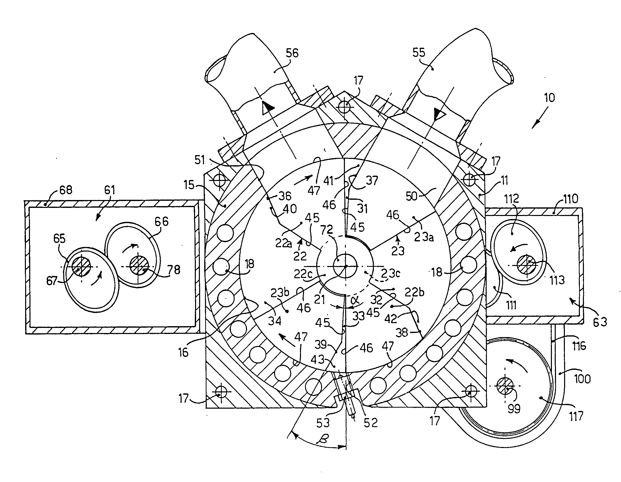
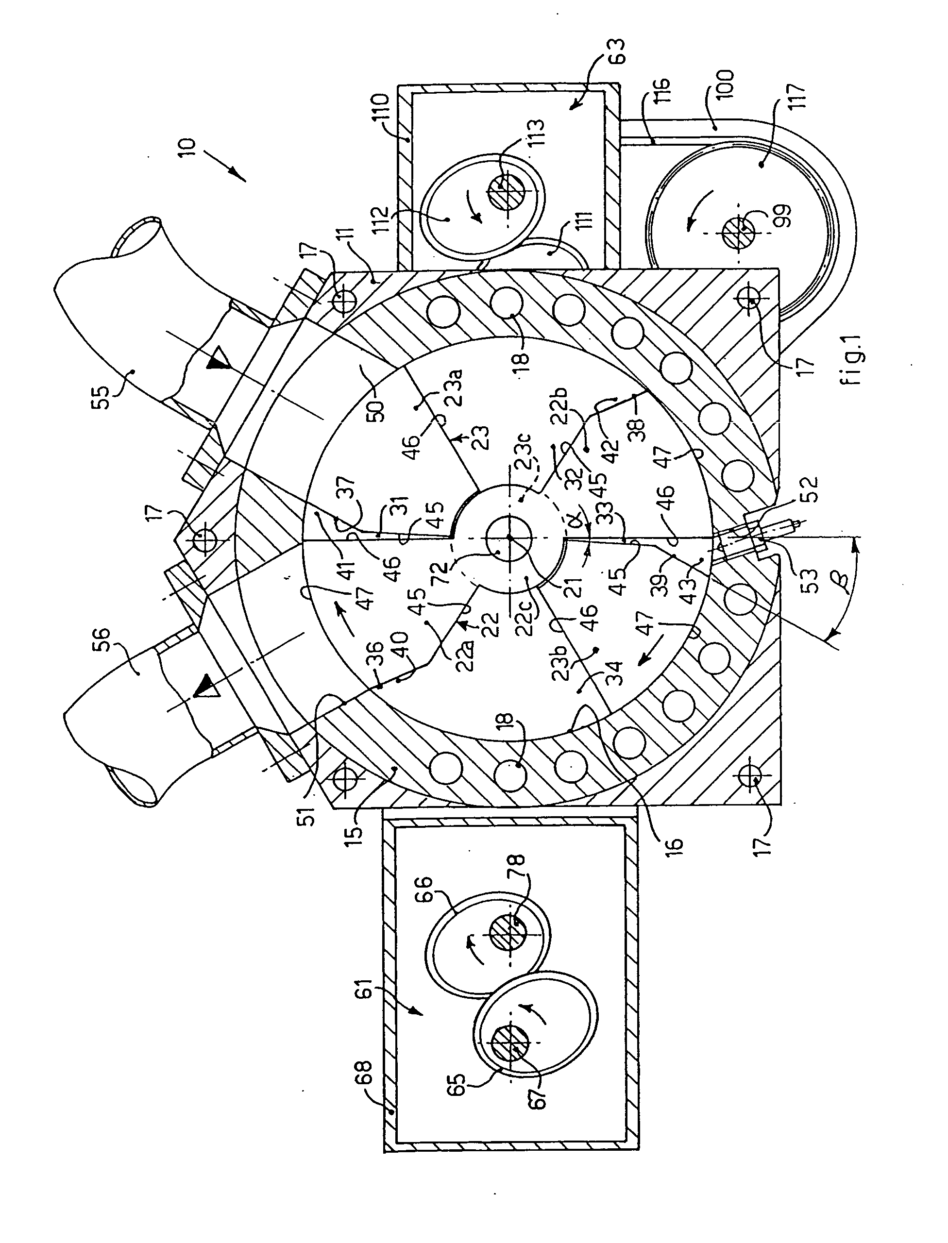
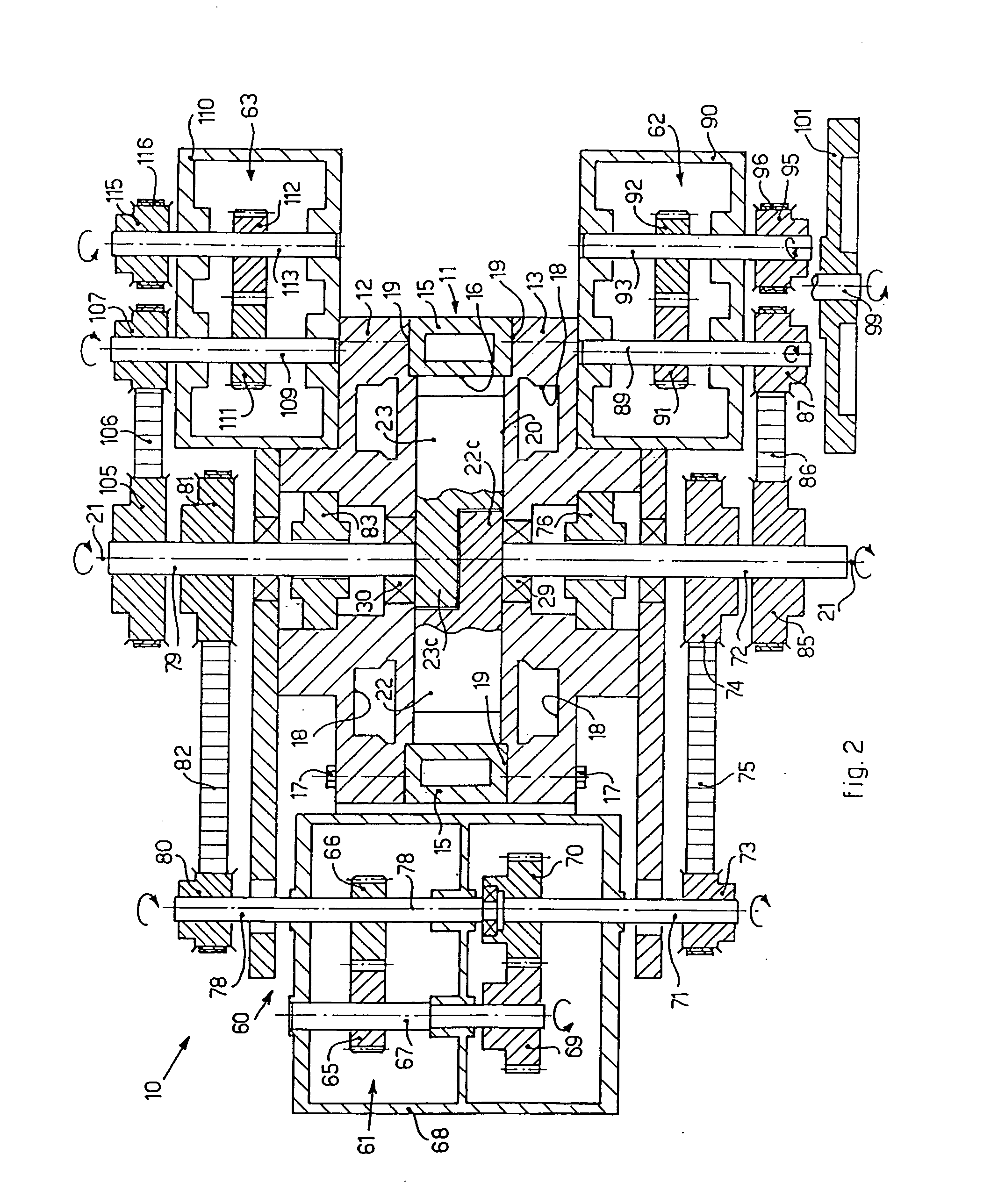
[0047]With reference to FIGS. 1, 2 and 3, a combustion engine 10 according to the present invention comprises a stator 11 essentially consisting of two metal lateral flanges 12 and 13, parallel to each other, and of a central spacer 15, also made of metal and shaped so as to define internally a cylindrical compartment 16. The flanges 12, 13 and the spacer 15 are provided internally with cooling channels 18 inside which, in any known manner, any cooling liquid is able to circulate, such as water or suchlike.

[0048]The two flanges 12, 13 and the spacer 15 are held together, with sealing packings 19 of a known type interposed, by means of bolts 17.

[0049]Inside the cylindrical compartment 16, two metal pistons 22 and 23 which constitute a rotor 20 are mounted rotatably, around the same axis of rotation.

[0050]The piston 22 is shaped so as to comprise a central part 22c and two radial arms 22a and 22b, diametrically opposite. In the same way, the piston 23 is shaped so as to comprise a cen...


PUM


Abstract

Combustion engine (10) comprising a stator (11) provided with a compartment (16), inside which a rotor (20) is mounted rotatable, which comprises two parts (22, 23) each comprising a peripheral surface (47) and articulated one with respect to the other and both mounted rotatable, around the same axis of rotation (21) substantially coaxial with the compartment (16). The combustion engine (10) comprises kinematisms (60) to coordinate cyclically the rotations of the two parts (22, 23) around the axis of rotation (21), so that each of the parts (22, 23) accelerates or decelerates synchronously with respect to the other, while still both rotating in the same direction and at the same average angular velocity. Each part (22, 23) comprises a first radial arm (22a, 23a, 22b, 23b) provided with a first lateral surface (45) orthogonal to the plane of rotation, to cooperate cyclically with a corresponding second lateral surface (46), also substantially orthogonal to the plane of rotation, a second adjacent radial arm (22a, 23a, 22b, 23b) to define a combustion chamber (31, 32, 33, 34). The first lateral surface (45) comprises a bevel (36, 37, 38, 39) oriented in the direction of the rotation, to define, with the second lateral surface (46) of the adjacent radial arm (22a, 23a, 22b, 23b), a combustion pre-chamber (40, 41, 42, 43) continuous with the combustion chamber (31, 32, 33, 34).

Description

FIELD OF THE INVENTION[0001]The present invention concerns a combustion engine comprising a stator having a substantially cylindrical compartment inside which a rotor is able to rotate, which comprises two parts that function as a piston, or two impellers which autonomously create the variations in volume using the walls of the disk from which the trapezoid pistons protrude. The two parts of the rotor are articulated one with respect to the other and are both mounted rotatable around the same axis of rotation substantially coaxial with the compartment of the stator. A kinematism is connected to the two pistons to coordinate cyclically their rotations around the same axis of rotation, so that each of the two pistons accelerates or decelerates synchronously with respect to the other, while they still both rotate in the same direction and at the same average angular speed. The two pistons also function as opening / closing valves for two intake and exhaust apertures, or gaps, communicati...

Claims


Application Information

Patent Timeline
Patent Type & Authority Applications(United States)
IPC IPC(8): F02B53/00
CPCF01C1/077F02B53/12Y02T10/17F02B55/14F02B55/02Y02T10/12
Inventor MANGANARO, MARIANO
Owner VALMAX
Why Eureka
Try Eureka