Pressure-adjustable multi-tube spraying device

a multi-tube, pressure-adjusting technology, applied in lighting and heating apparatus, combustion types, separation processes, etc., can solve the problems of increasing the power consumption of the compressor, affecting the quality of suction, and further damage, and achieves simple pressure control and uniform spray

Inactive Publication Date: 2010-06-10
IND TECH RES INST
View PDF13 Cites 12 Cited by
  • Summary
  • Abstract
  • Description
  • Claims
  • Application Information

AI Technical Summary

Benefits of technology

[0012]The present invention provides a multi-tube spraying device, which achieves uniform spray by simple pressure controlling.

Problems solved by technology

The incompletely evaporating refrigerant in the tubes will cause the liquid refrigerant to be sucked into the compressor and further damage it.
Consequently, it may yet lower the quality of suction and increase power consumption of the compressor.
However, the amount of the required refrigerant in flooded system is usually two times greater than that in a direct-expansion system, or even more.
The total cost of a flooded system is higher and it is also harmful to the environment.
However, the refrigerant in the liquid-vapor state is apt to distribute itself non-uniformly in the multi-tube spraying tubes 2111.
As a result, not only the manufacturing costs will be higher, but the quality will be affected by the complexity of the precise controlling and processing.
Furthermore, there is another issue coming from the pressure difference between the spraying tubes and that of the body, in which case the refrigerant may easily overflow out of the body.
However, the outlet 34 and the spraying device 30 are too close to each other so that the refrigerant vapor may bring the liquid refrigerant together to the compressor through the outlet 34, which causes the problem of the liquid being sucked by the compressor.
However, the configuration may cause a non-uniformly spray if the spraying device 44 is not horizontally setup.
In addition, the oversized spraying device 44 causes holdback for the refrigerant vapor to be transmitted into the compressor.
Besides, it is difficult to disassemble such structures which increases the maintenance cost.

Method used


Image

  • Pressure-adjustable multi-tube spraying device
  • Pressure-adjustable multi-tube spraying device
  • Pressure-adjustable multi-tube spraying device

Examples


Embodiment Construction

[0028]The specific embodiments are to be described to illustrate the present invention. These and other advantages or effects of the present invention can be easily appreciated by those ordinarily skilled in the art after reading the disclosure in the specification.

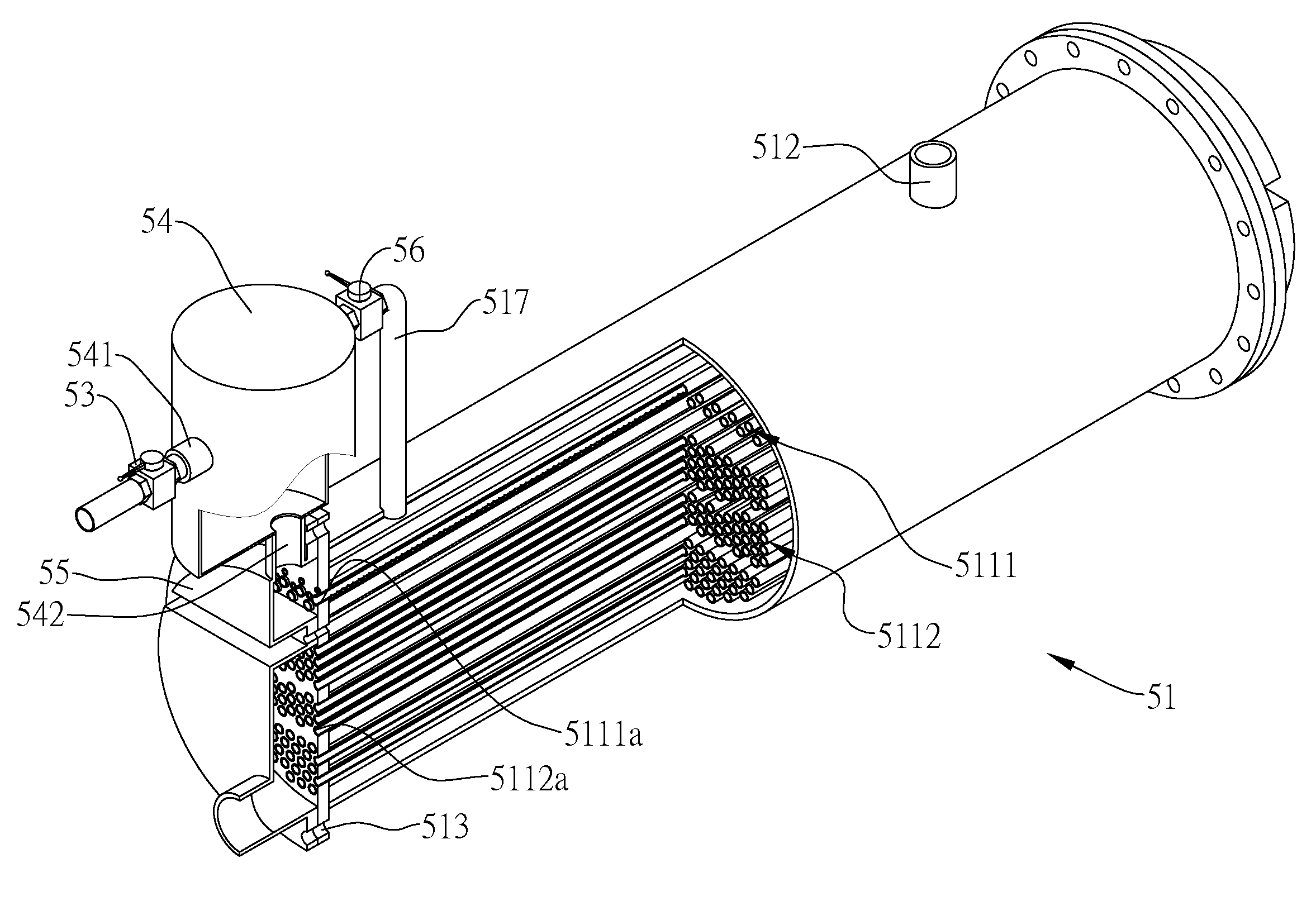
[0029]The schematic diagrams of the multi-tube spraying device according to the present invention are shown in FIGS. 5 and 6.

[0030]The basic component of the multi-tube spraying device is a body 51, comprising a first tube sheet 513 and a second tube sheet (not shown in FIGs.) disposed around the two ends of the body 51 respectively, an outlet pipe 512 for discharging refrigerant vapor from a vessel, a connecting pipe 517 for introducing the refrigerant vapor from a refrigerant source into the vessel, a plurality of openings 5111a and 5112a formed through the first tube sheet 513 and the second tube sheet, the vessel formed by the body 51 and the tube sheets, wherein a plurality of spraying tubes 5111 are disposed above a...


PUM


Abstract

A multi-tube spraying device is provided. The multi-tube spraying device includes a body having a closed vessel, wherein a plurality of spraying tubes are disposed in the upper part of the closed vessel and a plurality of heat exchanging tubes are disposed in the lower part of the closed vessel. The device further includes an outlet pipe for discharging refrigerant vapor contained therein and a connecting pipe for introducing the refrigerant vapor from a source to the vessel. In addition, a liquid-vapor separator connected to the refrigerant source separates the refrigerant into vapor and liquid for introducing the liquid refrigerant to the spraying tubes in the vessel while introducing the refrigerant vapor into the vessel. Therefore, a heat exchange is performed between the refrigerant and the heat exchanging tubes.

Description

BACKGROUND OF THE INVENTION[0001]1. Field of the Invention[0002]The present invention relates to a multi-tube spraying device, and more particularly, to a multi-tube spraying device used in a heat exchanger.[0003]2. Description of Related Art[0004]The mechanical refrigeration equipment usually includes the following four main components: compressors, condensers, expansion devices and evaporators, wherein the evaporators are used to make refrigerant to absorb heat, to evaporate, to enter the compressor, and to be compressed. The commercially available evaporating devices are usually operated in three types: direct-expansion, flooded, and spraying heat exchanging systems.[0005]The foresaid direct-expansion and flooded heat exchanging systems are heat exchangers combining a shell and inner tubes; the only difference between them is the fluid used for the shell side and the inner tubes. For direct-expansion heat exchanging systems, the target fluid for heat conduction flows through the ...

Claims


Application Information

Patent Timeline
Patent Type & Authority Applications(United States)
IPC IPC(8): F28B1/00F28D7/00B05C1/00
CPCF25B39/02F28D21/0017F28D7/16F28D3/02B01D1/0094B01D1/04B01D1/16B01D1/22
Inventor HUNG, KUO-SHULIU, CHUNG-CHELIU, CHIA-HUNGCHIANG, SHIH-CHANGLO, CHIN-HUNGCHIANG, HSU-CHENG
Owner IND TECH RES INST
Why Eureka
Try Eureka