Fluid processing system

a technology of processing system and flue, which is applied in the direction of filtration separation, multi-stage water/sewage treatment, separation process, etc., can solve the problems of product loss due to additional dead volume and additional cleaning costs, high investment costs, and long process times

Inactive Publication Date: 2010-06-10
PALL CORP
View PDF14 Cites 3 Cited by
  • Summary
  • Abstract
  • Description
  • Claims
  • Application Information

AI Technical Summary

Benefits of technology

[0012]The present invention advantageously makes use of modules which comprise a body of wound layers of a sheet material. Such modules are easily used with a fluid flow direction from the outer peripheral surface to the inner peripheral surface as well as a fluid flow direction from the inner peripheral surface to the outer peripheral surface. Backwashing of the modules and the system as a whole is greatly facilitated.
[0048]Preferably, the depth filter material is not only plastically or permanently deformable, but at least partly shows elastic properties so that upon compression of the sheet material, the elastic portion of the deformation helps to keep the adjacent layers of sheet material in close contact with one another, even if the surface of the sheet material may in its original state not be perfectly planar.

Problems solved by technology

Associated with these problems are high investment costs, long process times, additional costs for storage of equipment, product losses due to additional dead volume and additional cleaning costs, to name only the most important disadvantages.

Method used


Image

  • Fluid processing system
  • Fluid processing system
  • Fluid processing system

Examples


Embodiment Construction

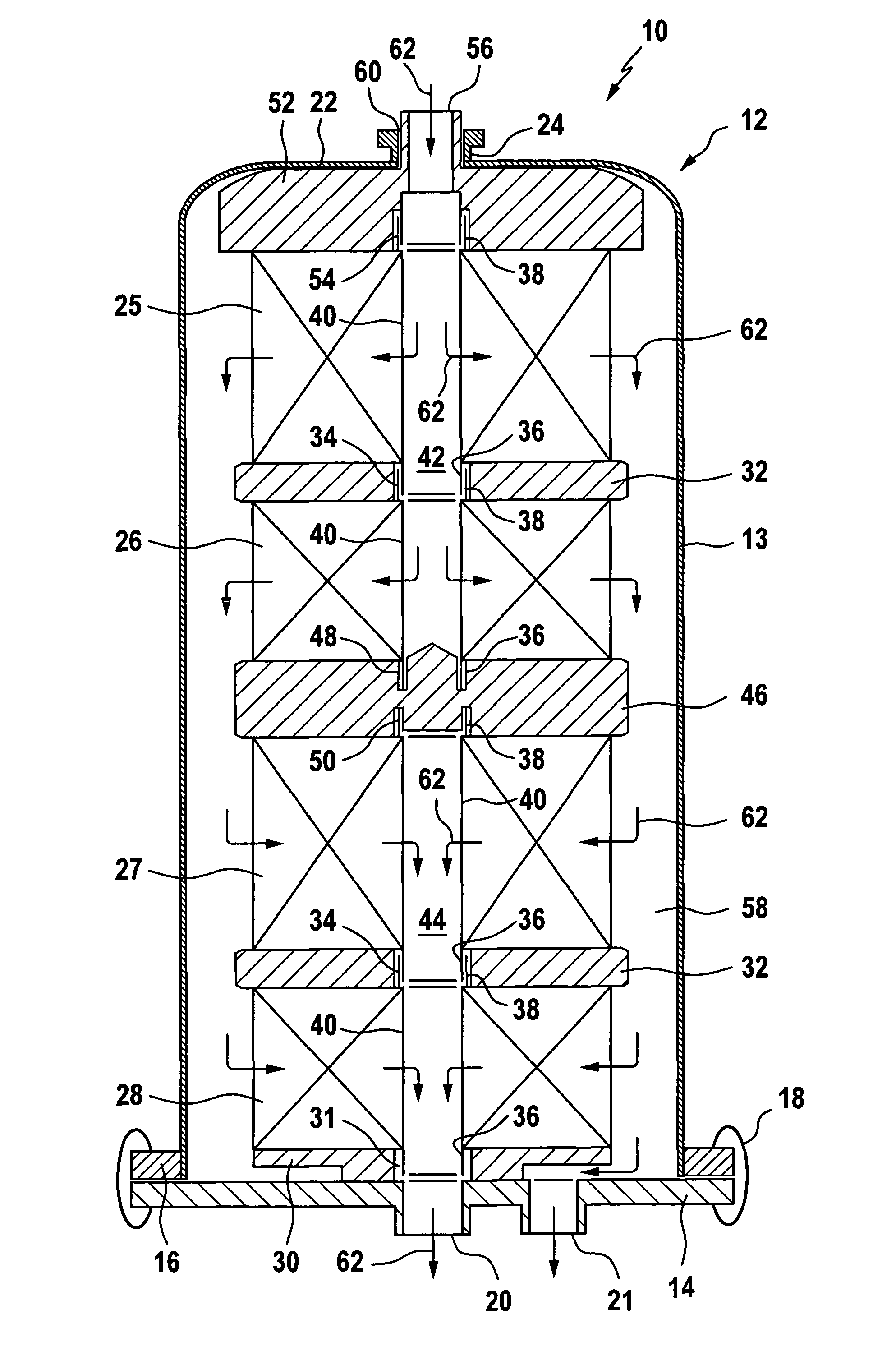
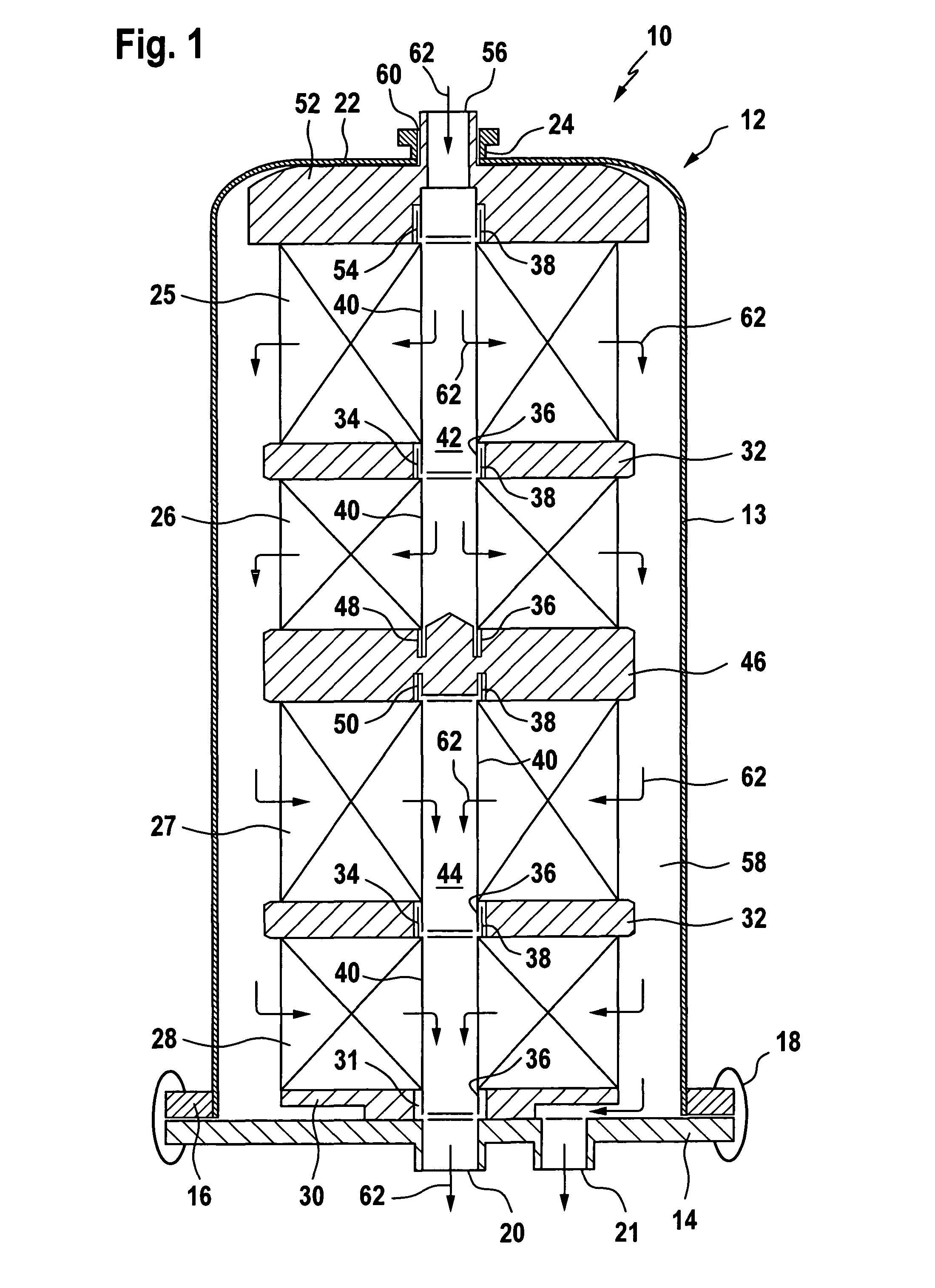
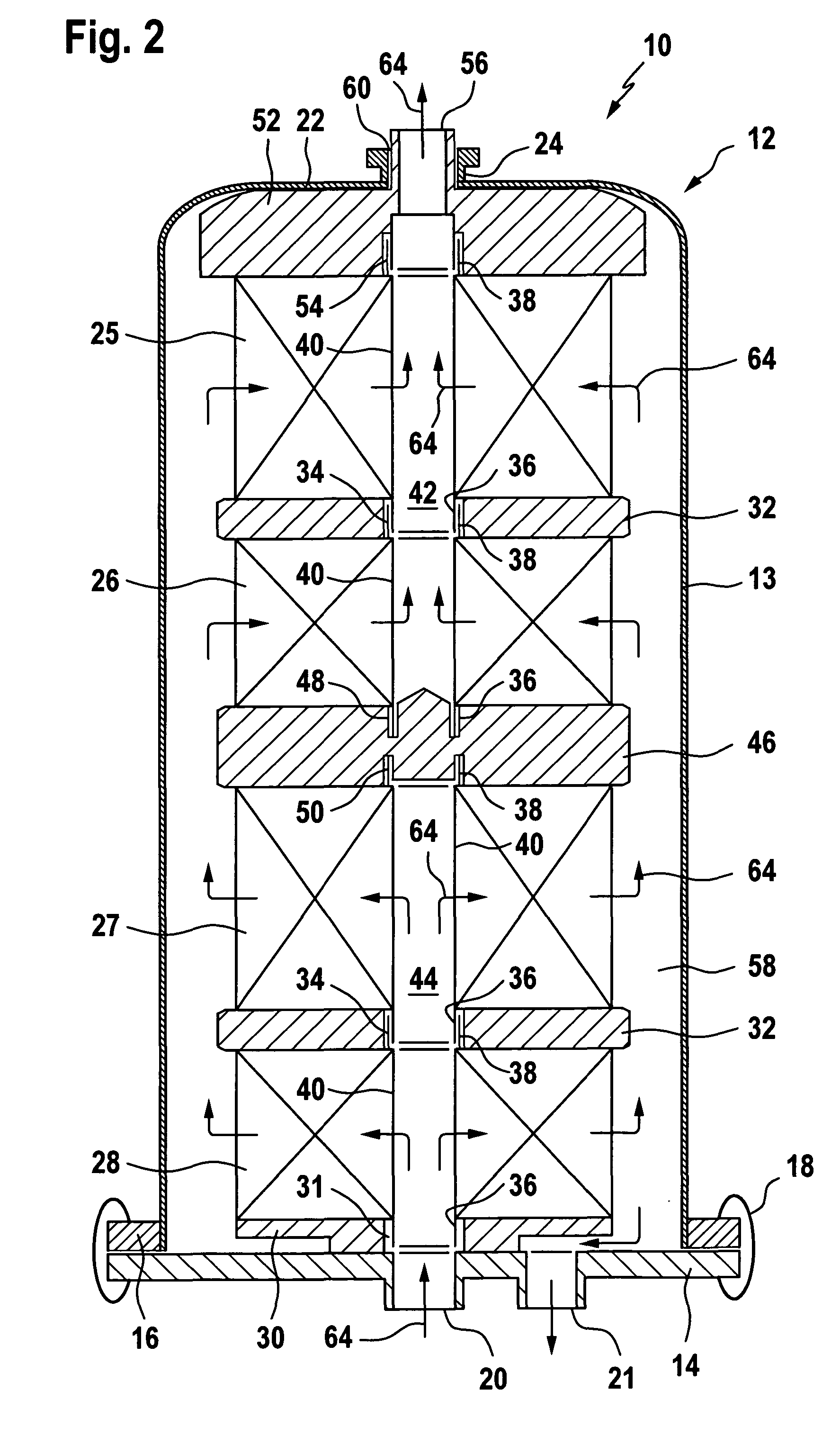
[0068]FIG. 1 shows a modular fluid processing system 10 comprising a cylindrical housing 12 in which four modules 25, 26, 27, 28 are accommodated one above another. The housing 12 with a cylindrical wall 13 comprises a bottom plate 14 which closes the lower open end of the cylindrical wall 13. The cylindrical wall 13 comprises at its lower open end a radially outwardly extending flange 16 to which the bottom plate 14 is connected by connecting means 18, for example, clamping screws, in a pressure-tight manner. At the center of the bottom plate 14 a central opening 20 and an off-center opening 21 are provided which are configured as line connectors and, depending on the flow direction, can serve as an inlet for the unprocessed fluid or an outlet for the processed fluid, respectively.

[0069]At the upper end of the cylindrical wall 13 of the housing 12 a top wall 22 is provided which closes the housing 12 at its upper end and is preferably integrally formed with the cylindrical wall 13....


PUM

PropertyMeasurementUnit
elastic forceaaaaaaaaaa
compression forceaaaaaaaaaa

Abstract

A fluid processing system comprising a housing (12) and at least one of a first type and at least one of a second type module, (25-28), The first and second modules having different fluid processing characteristics each module comprising a body of wound layers of a sheet material, said body having an inner and an outer peripheral surface, a first and a second end face, a passage (42, 44) extending along the winding axis of said body and in fluid communication with said inner peripheral surface, the passage of one of the first type and one of the second type modules being closed at one end thereof, said sheet material having a plurality of openings formed therein, said openings forming a first and a second type of channels within the wound layers of sheet material of said body, extending in a direction from the inner peripheral surface to the outer peripheral surface, the first type of channels being open at one end at said outer peripheral surface of the body and closed at the other end located adjacent to said inner peripheral surface, the second type of channels being open and closed at the respective other ends or closed at both ends, said channels of the one type being separated from the channels of the other type by portions of sheet material.

Description

FIELD OF THE INVENTION[0001]The present invention relates to a fluid treatment system useful in the multi-step processing of fluids, especially liquids, e.g. beverages or food oils.BACKGROUND OF THE INVENTION[0002]In many filtration applications, production and cleaning processes different process steps, especially different filtering steps are required.[0003]These steps are traditionally carried out separately, performing one step after the other. This is especially true for filtration processes, where the successful performance of the first filtration step is a prerequisite for the beginning of the second filtration step.[0004]This necessary sequence of steps quite often results in a process layout where each filtration step has its own design, starting from an own housing for the filter media, up to separate pumps and associated equipment and ending up possibly even in separate cleaning processes for the filtration equipment. This is especially true when so called closed systems ...

Claims


Application Information

Patent Timeline
Patent Type & Authority Applications(United States)
IPC IPC(8): B01D25/12B01D15/04
CPCB01D25/24B01D25/26B01D29/114B01D2201/40B01D29/117B01D29/54B01D29/58
Inventor DIEMER, WOLFGANGZEILER, MARTINFEIFEL, KLAUS
Owner PALL CORP
Why Eureka
Try Eureka