Image capturing apparatus and image capturing method

a technology of image capturing apparatus and image sensor, which is applied in the direction of color television details, television systems, radio control devices, etc., can solve the problems of image defects, contour blurring and false contour, and may occur in the combined image, etc., and achieve the effect of appropriately expanding the dynamic range of an image sensor

Inactive Publication Date: 2010-06-10
CANON KK
View PDF14 Cites 22 Cited by
  • Summary
  • Abstract
  • Description
  • Claims
  • Application Information

AI Technical Summary

Benefits of technology

[0011]The present invention is directed to an image capturing apparatus and an image capturing method which are capable of appropriately expanding the dynamic range of an image sensor.

Problems solved by technology

However, the position displacement may occur due to the time difference between the shots in the combined image, so that image defects, such as contour blurring and false contour, may occur in the combined image.
Therefore, if a luminance range of a scene is wider than the dynamic range that can be captured by the low sensitivity region, it may cause a loss of highlight detail, so that the effect of expanding the dynamic range becomes insufficient.
However, since the method sets a sensitivity difference on the sensor by the fixed pattern, sampling points in both the low sensitivity region and the high sensitivity region become less as compared to a conventional RGB sensor.
Moreover, by using a fixed pattern regardless of the object luminance, noise increases in a pixel corresponding to the low sensitivity region.
It is thus difficult to increase the number of pixels and bits.
Furthermore, since the charge generated in the photodiode is continuously transferred to a floating diffusion, the noise generated in the floating diffusion cannot be eliminated, so that noise tolerance is low.
Therefore, it is difficult to appropriately expand the dynamic range of the image sensor using the conventional techniques.

Method used


Image

  • Image capturing apparatus and image capturing method
  • Image capturing apparatus and image capturing method
  • Image capturing apparatus and image capturing method

Examples


Embodiment Construction

[0042]Various exemplary embodiments, features, and aspects of the invention will be described in detail below with reference to the drawings.

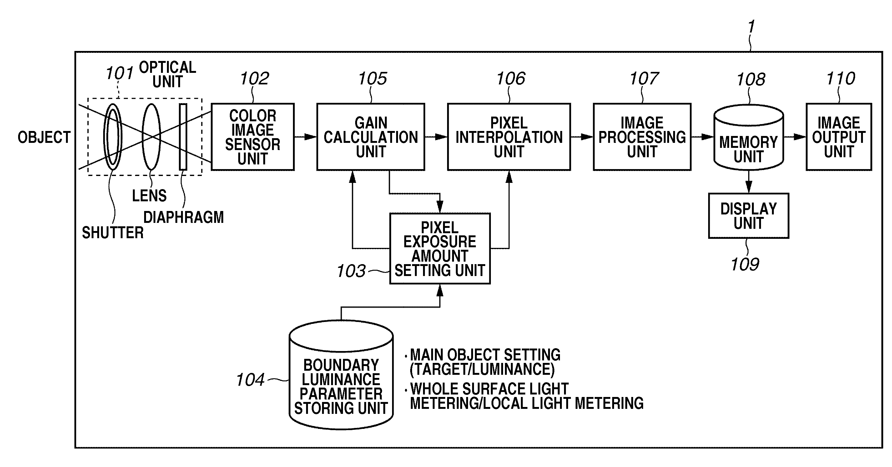
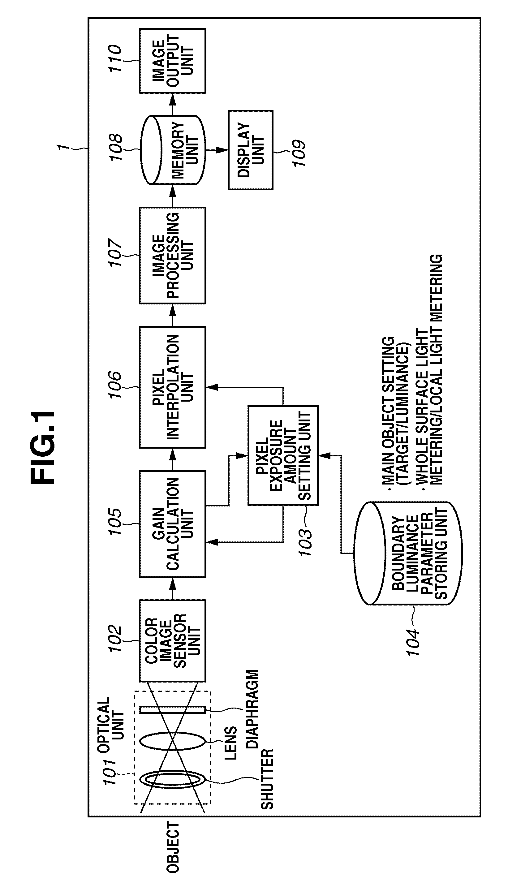
[0043]FIG. 1 illustrates a block diagram of a configuration of an image capturing apparatus according to the first exemplary embodiment of the present invention.

[0044]Referring to FIG. 1, an image capturing apparatus 1 according to the present exemplary embodiment includes an optical unit 101, a color image sensor unit 102, a pixel exposure amount setting unit 103, a boundary luminance parameter storing unit 104, a gain calculation unit 105, a pixel interpolation unit, an image processing unit 107, and a memory unit 108. Further, the image capturing apparatus 1 includes a display unit 109 and an image output unit 110.

[0045]The optical unit 101 includes a shutter, a lens, a diaphragm, and an optical low-pass filter (LPF). The color image sensor unit 102 includes color filters of a plurality of colors arranged in a mosaic form and complementary m...


PUM


Abstract

An image capturing apparatus includes an image capturing unit including a plurality of pixels adjacently disposed in a horizontal direction and a vertical direction and configured to perform photoelectric conversion on received light to accumulate electric charge, and a pixel exposure control unit configured to set an exposure amount of each of the plurality of pixels based on a result of capturing an image by the image capturing unit and to control an exposure time of each of the plurality of pixels.

Description

BACKGROUND OF THE INVENTION[0001]1. Field of the Invention[0002]The present invention relates to an image capturing apparatus and an image capturing method directed to expanding the dynamic range.[0003]2. Description of the Related Art[0004]In general, the dynamic range of an image sensor used in a digital single-lens reflex camera, compact digital camera, and digital video camera is small as compared to the dynamic range of the real world. Therefore, conventionally, studies have been conducted to expand the dynamic range of the image sensor. Such methods include multiple sampling by taking a plurality of shots, one-shot sampling using a fixed pattern, and exposure time control according to object luminance.[0005]In the method of multiple sampling by taking a plurality of shots, a plurality of images is captured with the exposure time gradually changed to acquire information on the dynamic range. After capturing the images, gain correction is performed on pixel values of each image ...

Claims


Application Information

Patent Timeline
Patent Type & Authority Applications(United States)
IPC IPC(8): H04N5/235H01L27/146H04N5/335H04N5/353H04N5/355H04N5/374H04N5/3745H04N5/376
CPCH04N5/23248H04N5/3745H04N5/35554H04N23/68H04N25/583H04N25/77
Inventor ARAI, KIMITAKA
Owner CANON KK
Why Eureka
Try Eureka