
Data communication system, data communication request device, and data communication response device

a data communication and request device technology, applied in the field of data communication systems, data communication request devices, and data communication response devices, can solve the problems of waste of communication bandwidth allocated for other functions that are inactive, and achieve the effect of reducing communication efficiency

Inactive Publication Date: 2010-06-10
PANASONIC CORP
View PDF12 Cites 261 Cited by
  • Summary
  • Abstract
  • Description
  • Claims
  • Application Information

AI Technical Summary

Benefits of technology

[0012]According to the above structure, since each of the first and second devices in the data communication system uses the first communication flag, the second communication flag, and the procedure predetermined between the devices, the both devices are able to select the identical communication scheme. Further, since data communication between the both devices cannot be commenced without handshaking between the request signal and the response signal that determines the communication scheme, the present invention makes it possible to determine the communication scheme conforming to the capability of each of the devices, without an additional procedure required for determination of the communication scheme. As a result, the occurrence of the underflow of transmit buffer and the overflow of receive buffer as mentioned in the problem description is suppressed in the data communication system, and therefore data communication is performed without a decrease in communication efficiency.
[0013]Here, prior to generating the request signal, the communication request unit may generate a priority flag in accordance with the capability of each device, store the generated priority flag in a predetermined first storage area, and transmit it to the second device, the priority flag indicating either the first device is to take priority or the second device is to take priority in accordance with the capability of each device, upon reception of the priority flag, the communication response unit may store the received priority flag in a predetermined second storage area, and the procedure may include the steps of judging whether an indication of the first communication flag accords with an indication of the second communication flag, and when judging affirmatively, selecting a communication scheme in accordance with the indication, and when judging negatively, causing the first and second selection units to select a communication scheme indicated by the communication flag generated by one of the devices which is to take priority, depending on the priority flags stored in the first and second storage areas respectively.
[0014]According to the above structure, since the first and second devices share the priority flag and select the communication scheme according to the indication, it is prevented that the devices select different communication schemes from each other when the indication of the first communication flag differs from the indication of the second communication flag.
[0015]Here, the capability may include a buffer capacity used for data reception, the request signal may include a communication type indicating either that the first device requests to transmit data or that the first device requests to receive data, the communication request unit may judge whether each device has a buffer capacity sufficient enough to secure an amount of data that is to be transmitted in a half-duplex communication bandwidth, and when judging affirmatively, generate a priority flag indicating that a data transmitting device is to take priority, and when judging negatively, generate a priority flag indicating a data receiving device is to take priority, the first and second selection unit may select, when the priority flag indicates that the data transmitting device is to take priority, a communication scheme indicated by a communication flag generated by the data transmitting device depending on the communication type, and select, when the priority flag indicates that the data receiving device is to take priority, a communication scheme indicated by a communication flag generated by the data receiving device depending on the communication type.
[0016]According to the above structure, when the indication of the first communication flag differs from the indication of the second communication flag, the first and second devices select the communication scheme in accordance with the indication of the communication flag transmitted from either a data transmitting device or a data receiving device, with use of the priority flag determined by the receive buffer capacity in each of the devices. Accordingly, the present invention makes it possible, in the data communication system, to prevent the overflow of the buffer in the receiving device when the priority flag indicates the receiving device, and to make the most use of the send capability of a sending device when the priority flag indicates the sending device.
[0017]Here, the communication request unit may receive information with respect to the capability of the second device, compare the capability indicated by the received information with the capability of the first device, and generate a priority flag indicating that one of the devices having the capability inferior to the other is to take priority according to a comparison result of the initialization unit, and the first and second selection units may select, when the priority flag indicates that the first device is to take priority, a communication scheme indicated by the first communication flag, and select, when the priority flag indicates that the second device is to take priority, a communication scheme indicated by the second communication flag.

Problems solved by technology

In general, although the full-duplex communication scheme, which is easy to control, allows for communication at a higher speed, it has the following drawback.
That is, while either a send function or a receive function operates in the full-duplex communication scheme, there is waste of the communication bandwidth that is allocated for the other function that is inactive.

Method used


Image

  • Data communication system, data communication request device, and data communication response device
  • Data communication system, data communication request device, and data communication response device
  • Data communication system, data communication request device, and data communication response device

Examples


first embodiment

1. First Embodiment

[0063]Description will be made below on a communication device of the present invention with reference to figures.

Structure of Data Communication System 10

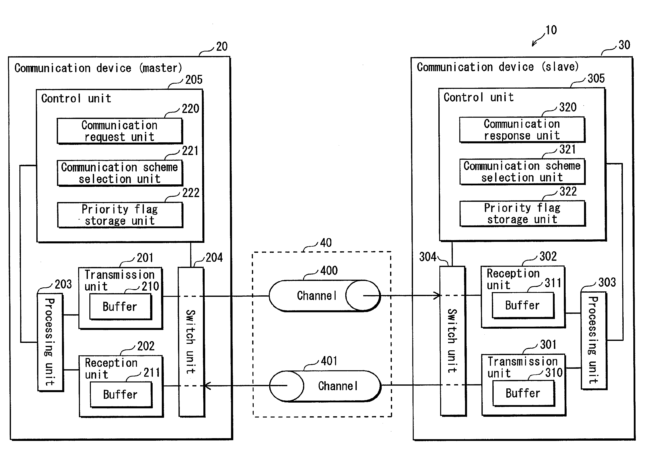
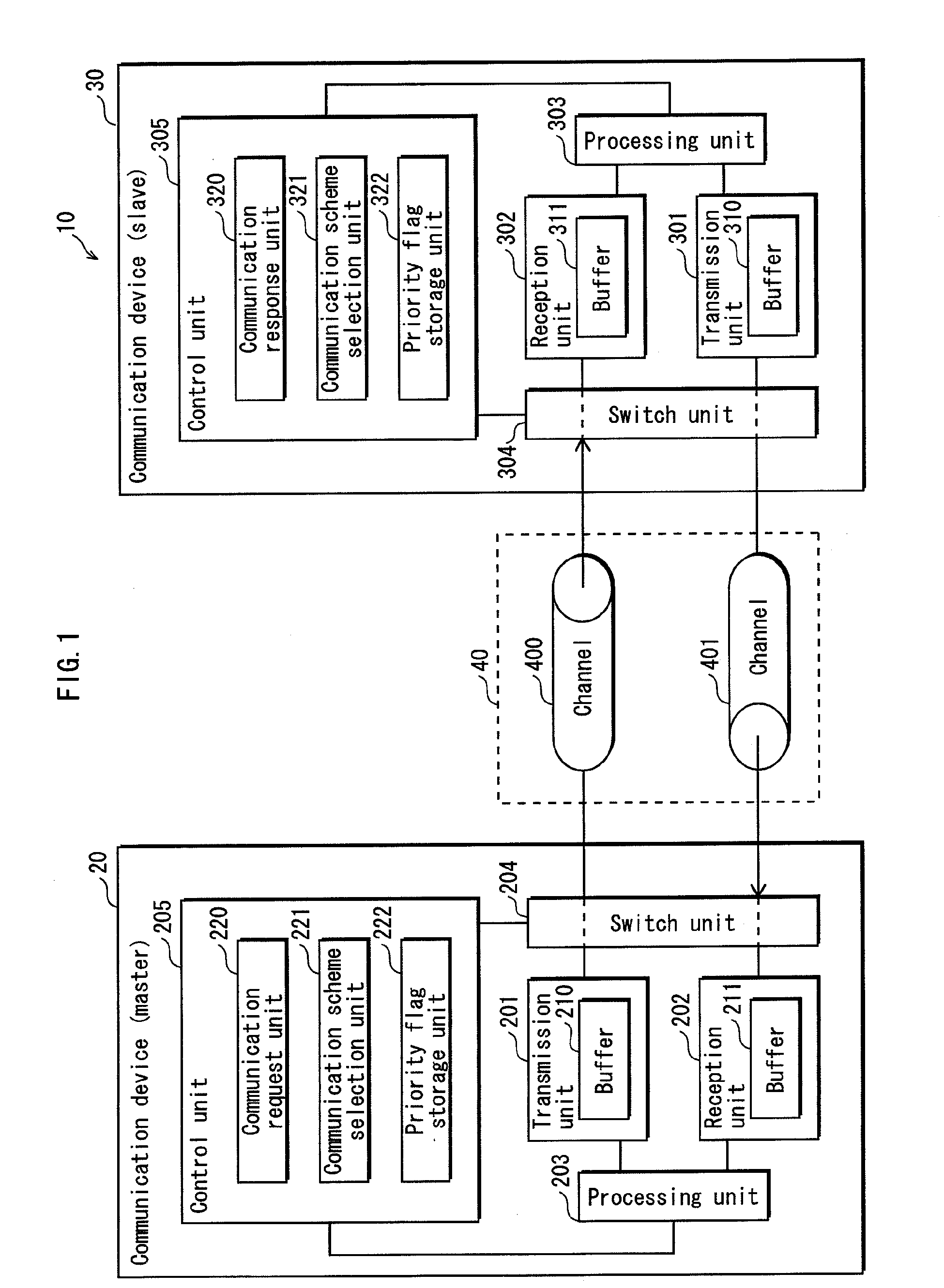
[0064]FIG. 1 shows a general structure of a data communication system 10 according to an embodiment of the present invention.

[0065]As shown in FIG. 1, the data communication system 10 comprises a communication device (master) 20, a communication device (slave) 30, and a set of channels 40.

[0066]The set of channels 40 comprises channels 400, 401, and realizes full-duplex communication and half-duplex communication between the master 20 and the slave 30.

[0067]The master 20 is a device that outputs a request signal as a trigger for commencement of communication. On the other hand, the slave 30 is a device that outputs, in response to the request signal, a response signal to the master 20 when it is ready for communication. In addition, in the present embodiment, the relation between the master 20 and the slave 30 ...


PUM


Abstract

The object of the present invention is to provide a data communication system in which a communication scheme is switched without a decrease in communication efficiency.In a data communication system including first and second devices that are capable of performing full-duplex communication and half-duplex communication via a set of channels connecting the first and second devices, the first device transmits, via the set of channels, to the second device a first communication flag indicating whether half-duplex communication is to be specified in accordance with a communication processing capability of the first device, the second device transmits, via the set of channels, to the first device a second communication flag indicating whether half-duplex communication is to be specified in accordance with a communication processing capability of the second device, and the first and second devices select either a full-duplex communication scheme or a half-duplex communication scheme depending on the first and second communication flags in compliance with a procedure predetermined between the devices and perform data communication in the selected communication scheme, the selected communication scheme conforming to the communication processing capability of each device.

Description

TECHNICAL FIELD[0001]The present invention relates to an art for selecting a communication method in a data communication system including a plurality of communication devices that are connected via a set of channels capable of full-duplex communication and half-duplex communication.BACKGROUND ART[0002]Along with recent miniaturization and development of high speed processing technologies of semiconductor devices, a data amount that is communicated among apparatuses, or among LSIs mounted on an apparatus, is becoming all the more larger, whereas there still exist rigid restrictions on the number of LSI terminals (pads) which influences LSI package cost.[0003]The communication modes used under such restrictions include a half-duplex communication scheme and a full-duplex communication scheme. In general, although the full-duplex communication scheme, which is easy to control, allows for communication at a higher speed, it has the following drawback. That is, while either a send funct...

Claims


Application Information

Patent Timeline
IPC IPC(8): H04B1/44
CPCH04L5/14H04W72/1247H04L5/16H04L5/1438H04W72/566
Inventor NISHIOKA, SHINICHIROSAKAI, KEISUKETOYAMA, MASAYUKISEKIBE, TSUTOMU
Owner PANASONIC CORP
Learn More