Multi-carrier signal transmitter, multi-carrier signal receiver, and method of transmitting and receiving multi-carrier signal

a multi-carrier signal and receiver technology, applied in the direction of digital transmission, transmission path division, baseband system details, etc., can solve the problems of digital interference between the higher layer component and the lower layer component of the multi-carrier signal

Inactive Publication Date: 2010-06-10
PANASONIC CORP
View PDF6 Cites 12 Cited by
  • Summary
  • Abstract
  • Description
  • Claims
  • Application Information

AI Technical Summary

Benefits of technology

[0007]The present invention provides a multi-carrier signal transmitter, a multi-carrier signal receiver, a method of transmitting multi-carrier signal as well as a method of receiving multi-carrier signal that are capable of transferring a hierarchical multi-carrier signal without causing digital interference between a higher layer component and a lower layer component of the multi-carrier signal.

Problems solved by technology

It therefore has a problem that a higher layer component and a lower layer component of the multi-carrier signal digitally interfere with each other.

Method used


Image

  • Multi-carrier signal transmitter, multi-carrier signal receiver, and method of transmitting and receiving multi-carrier signal
  • Multi-carrier signal transmitter, multi-carrier signal receiver, and method of transmitting and receiving multi-carrier signal
  • Multi-carrier signal transmitter, multi-carrier signal receiver, and method of transmitting and receiving multi-carrier signal

Examples


first exemplary embodiments

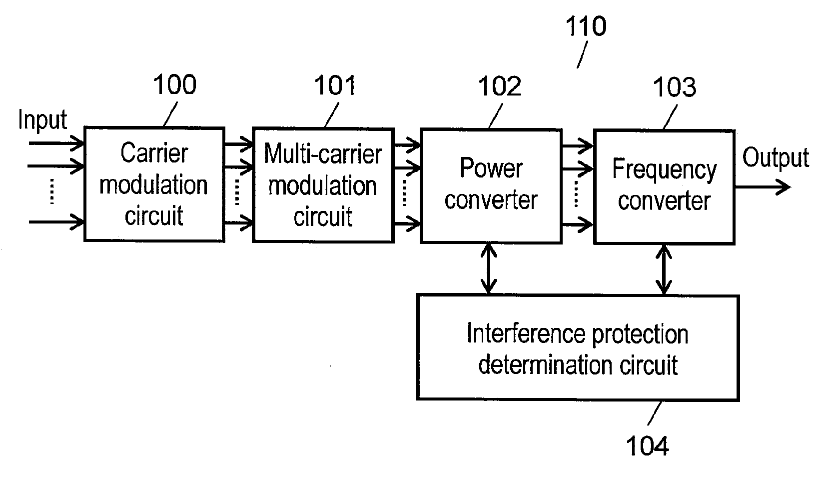
[0048]FIG. 1 is a block diagram showing one example of multi-carrier signal transmitter according to the first exemplary embodiment of this invention.

[0049]In FIG. 1, multi-carrier signal transmitter 110 includes carrier modulation circuit 100, multi-carrier modulation circuit 101, power converter 102, frequency converter 103 and interference protection determination circuit 104. Carrier modulation circuit 100 receives a plurality of input signals for carrier modulation, and outputs a plurality of carriers. Multi-carrier modulation circuit 101 receives the plurality of carriers output from carrier modulation circuit 100, and outputs a plurality of multi-carrier signals. These multi-carrier signals are comprised of a plurality of carriers multiplexed along a frequency axis, which are transmitted in parallel. Power converter 102 receives the plurality of multi-carrier signals output from multi-carrier modulation circuit 101, and outputs the plurality of multi-carrier signals after inc...

second exemplary embodiment

[0069]FIG. 7 is a block diagram of multi-carrier signal transmitter 710 representing one example according to the second exemplary embodiment of this invention. Like reference marks are used in FIG. 7 to designate like structural components as those of FIG. 1, and their details will be skipped.

[0070]In FIG. 7, variable amplifier 700 receives a plurality of multi-carrier signals output from multi-carrier modulation circuit 101, and outputs the plurality of multi-carrier signals after increasing a level of their amplitude. When the level of amplitude is increased, their power level also increases. Variable attenuator 701 receives the plurality of multi-carrier signals output from variable amplifier 700, and outputs the plurality of multi-carrier signals after decreasing a level of their amplitude. When the level of amplitude is decreased, their power level also decreases. Frequency processor 702 receives the plurality of multi-carrier signals output from variable attenuator 701, and o...

third exemplary embodiment

[0091]Description is provided for a multi-carrier signal receiver according to the third exemplary embodiment of this invention with reference to FIG. 9.

[0092]As shown in FIG. 9, multi-carrier signal receiver 900 of the third exemplary embodiment includes frequency inverter 910, power inverse converter 920, multi-carrier demodulation circuit 930 and carrier modulation circuit 940. This multi-carrier signal receiver 900 carries out processes in reverse of those executed by any of multi-carrier signal transmitter 110 shown in FIG. 1 and multi-carrier signal transmitter 710 shown in FIG. 7.

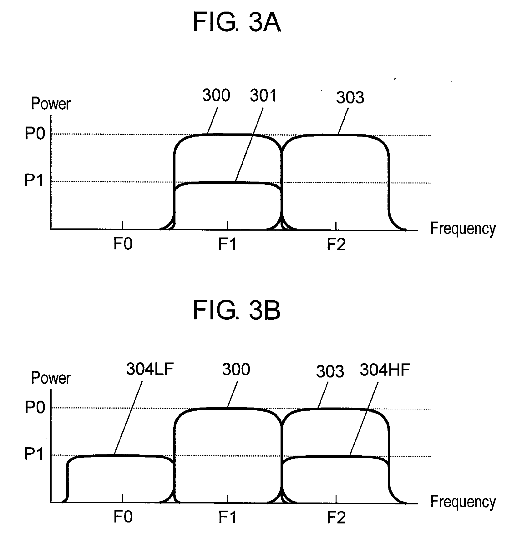
[0093]Frequency inverter 910 inverts a frequency of received signals when needed. That is, frequency inverter 910 has a function of inverting a center frequency of the received multi-carrier signals if the center frequency is found converted at the time of transmission to recover the original center frequency. In the case of receiving lower layer component 304HF or lower layer component 304LF of the ...


PUM


Abstract

A multi-carrier signal transmitter includes a multi-carrier modulation circuit, a power converter, a frequency converter and an interference protection determination circuit, and that the interference protection determination circuit determines a difference in power levels between a higher layer component and a lower layer component of multi-carrier signals in a manner to avoid digital interference. The power converter converts a power level of the multi-carrier signals when necessary based on a data of the determination, and the frequency converter converts a center frequency band of the multi-carrier signals when necessary based on the data of the determination. The digital interference of the hierarchical multi-carrier signals can be prevented.

Description

TECHNICAL FIELD[0001]The present invention relates to a multi-carrier signal transmitter, a multi-carrier signal receiver, a method of transmitting multi-carrier signal as well as a method of receiving multi-carrier signal that are capable of transmitting and / or receiving hierarchical multi-carrier signals without causing digital interference.BACKGROUND ART[0002]A conventional multi-carrier signal transmitter capable of transmitting hierarchical signals allocates a power level and a modulation method to each individual carrier in order to improve reliability of the hierarchical transmission. A multi-carrier signal transmitter of this kind is disclosed in patent document 1 for example. This method of allocating power levels is to allocate the power levels in a sequentially order during the multi-carrier modulation to equalize power spectral densities of the hierarchical multi-carrier signals, thereby preventing interference with other services. Likewise, this method of allocating mod...

Claims


Application Information

Patent Timeline
Patent Type & Authority Applications(United States)
IPC IPC(8): H04L25/03H04L27/06H04L27/00
CPCH04L5/0007H04L27/2604H04L27/3488H04L27/2647H04L27/2626
Inventor UEDA, YOSHIAKITAKAHASHI, HIDEKI
Owner PANASONIC CORP
Why Eureka
Try Eureka