Image processing device for determining cut lines and related methods

Inactive Publication Date: 2010-06-10
HARRIS CORP
View PDF17 Cites 19 Cited by
  • Summary
  • Abstract
  • Description
  • Claims
  • Application Information

AI Technical Summary

Benefits of technology

[0011]In view of the foregoing background, it is therefore an object of the present in

Problems solved by technology

Indeed, during this registration process, it is not uncommon for there to be significant overlapping portions between images.
Before registration of the images for a mosaic image, the images are typ

Method used


Image

  • Image processing device for determining cut lines and related methods
  • Image processing device for determining cut lines and related methods
  • Image processing device for determining cut lines and related methods

Examples


Embodiment Construction

[0036]The present invention will now be described more fully hereinafter with reference to the accompanying drawings, in which preferred embodiments of the invention are shown. This invention may, however, be embodied in many different forms and should not be construed as limited to the embodiments set forth herein. Rather, these embodiments are provided so that this disclosure will be thorough and complete, and will fully convey the scope of the invention to those skilled in the art. Like numbers refer to like elements throughout.

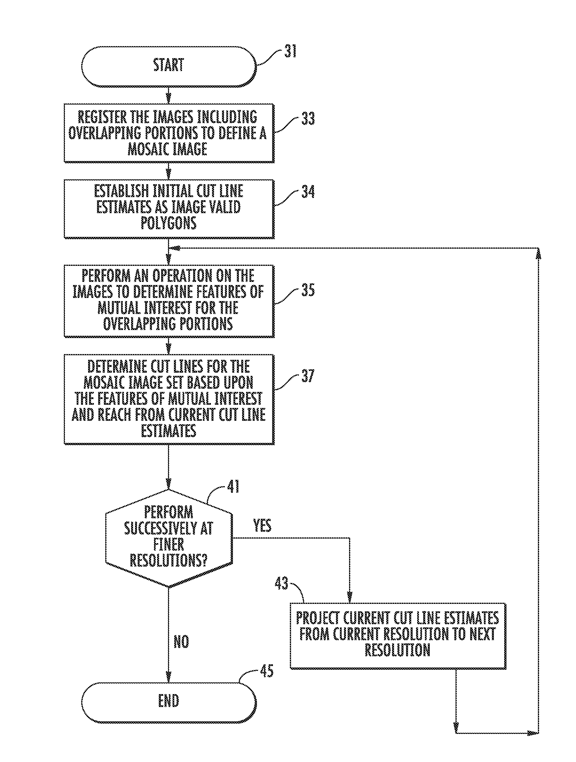
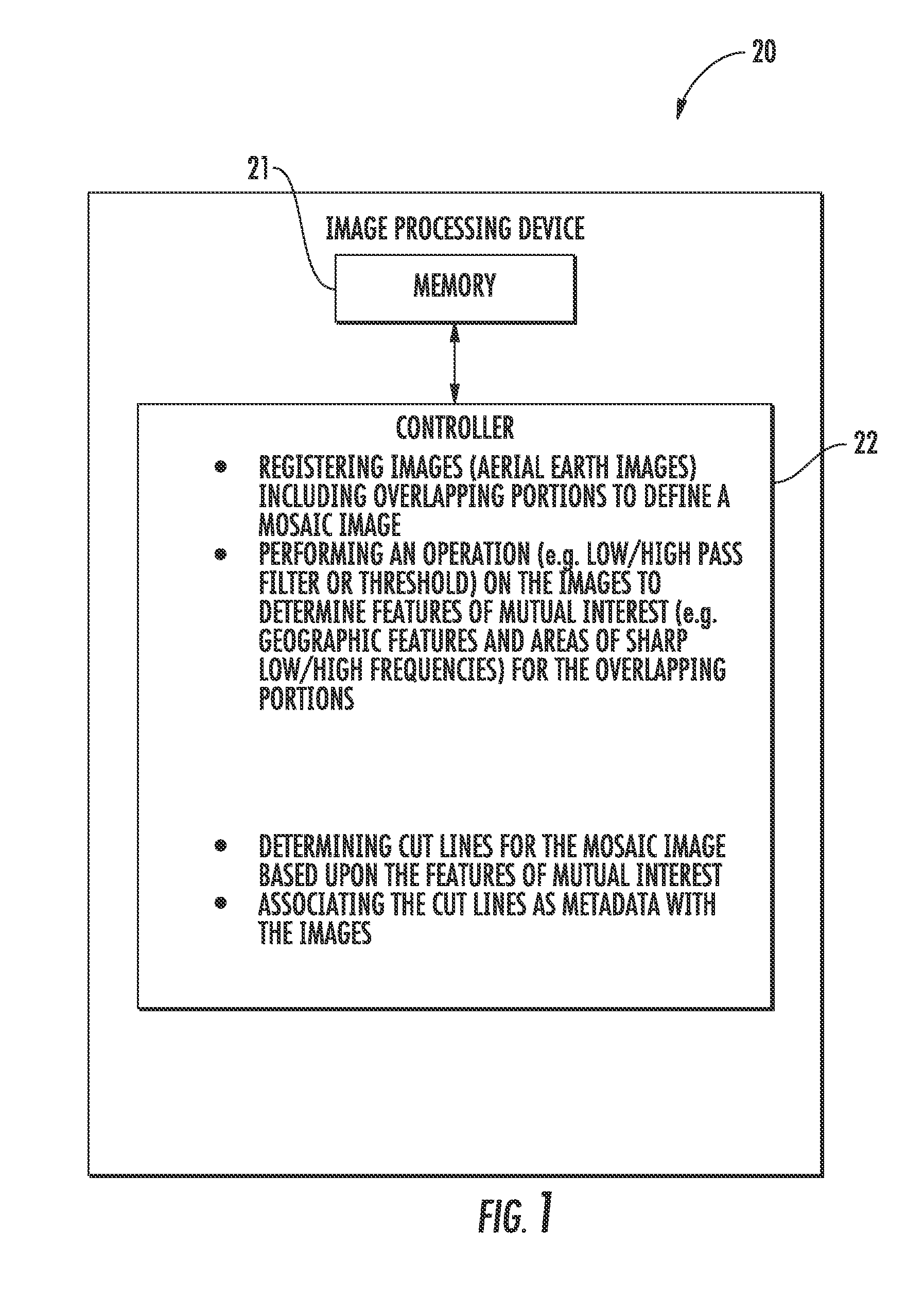
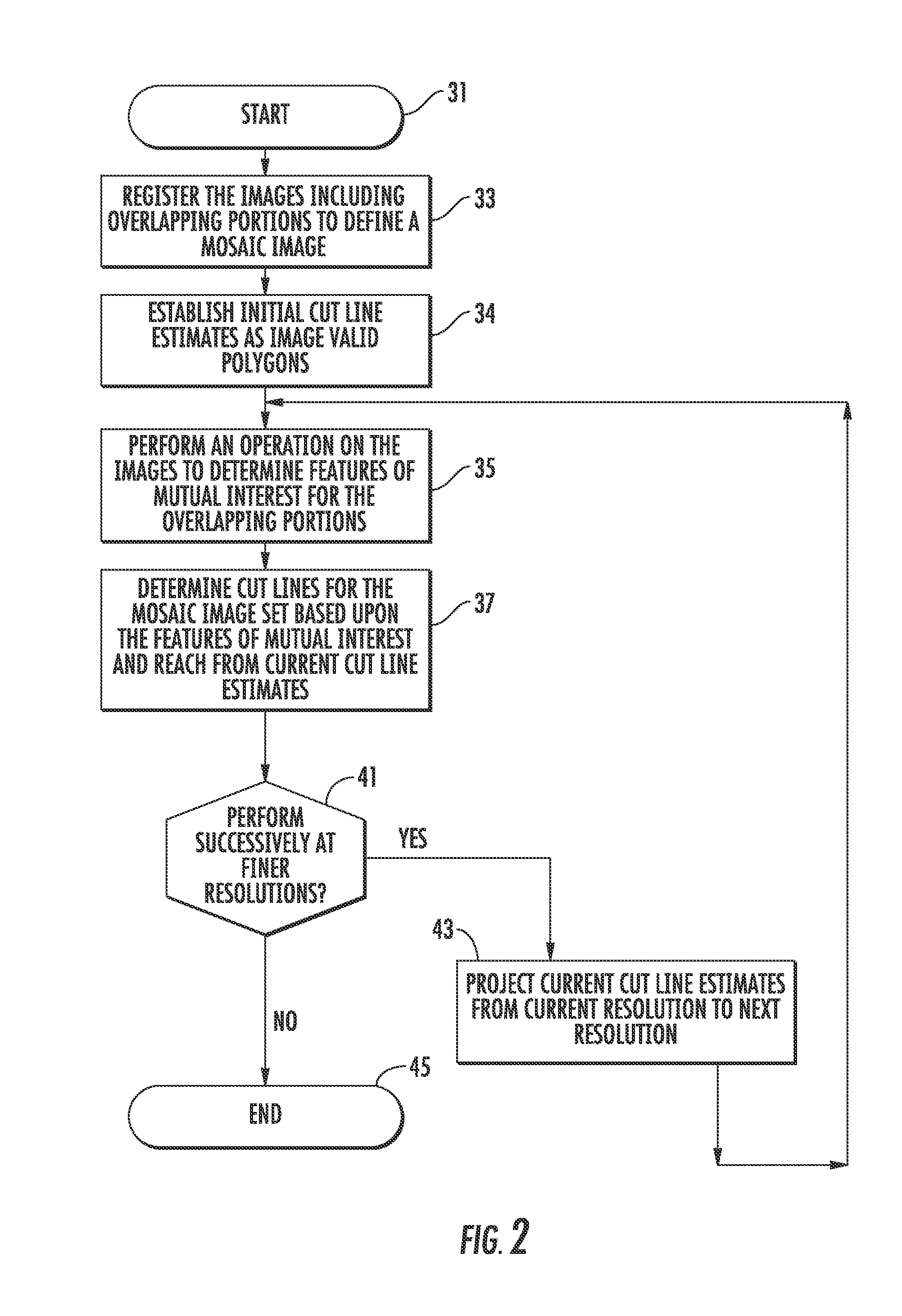
[0037]Referring initially to FIGS. 1-3, an image processing device 20 and a computer implemented method for processing a plurality of images 71-73 according to the present invention are now described with reference to a flowchart 30. The method begins at Block 31. The image processing device illustratively includes a memory 21, and a controller 22, which may include a central processing unit (CPU) of a PC, Mac, or other computing workstation, for example. ...


PUM


Abstract

An image processing device may include a memory, and a controller cooperating with the memory for registering images including overlapping portions to define a mosaic image. The controller may also perform an operation on the images to determine features of mutual interest for the overlapping portions, and determine cut lines for the mosaic image based upon the features of mutual interest for the overlapping portions.

Description

GOVERNMENT LICENSE RIGHTS[0001]The United States Government was given two (2) site-licensed copies for the Harris ORIGIN tool software in this invention. This was provided with Restricted Rights per the terms contained in the contract No. 2003-K-068250-000, which was awarded by the National Geospatial-Intelligence Agency. Harris retained the right to sell licenses for the defined software functions on future Government programs.FIELD OF THE INVENTION[0002]The present invention relates to the field of image processing, and, more particularly, to processing mosaic images and related methods.BACKGROUND OF THE INVENTION[0003]In certain applications, detailed imagery of large and expansive surfaces may be needed. These applications may include geographic satellite mapping, for example, where imagery of portions of the Earth's surface are gathered via satellite. A typical approach for displaying the expansive data in these applications is a mosaic image. The typical mosaic image may be fo...

Claims


Application Information

Patent Timeline
IPC IPC(8): G06K9/40G06K9/32
CPCG06T7/0083G06T3/4038G06T7/12
Inventor DAMKJER, KRISTIAN LINNELSTROM, MARK D.
Owner HARRIS CORP
Why Eureka
Try Eureka