Optical transmission apparatus with stable optical signal output

a transmission apparatus and stable technology, applied in the direction of electromagnetic transmission, electrical equipment, transmission, etc., can solve the problem of reducing the demand for high-speed electrical devices transmission ra

Inactive Publication Date: 2010-06-10
ELECTRONICS & TELECOMM RES INST
View PDF8 Cites 80 Cited by
  • Summary
  • Abstract
  • Description
  • Claims
  • Application Information

AI Technical Summary

Benefits of technology

[0009]According to an exemplary aspect, there is provided an optical transmission apparatus, including: an optical modulator which includes first and second modulators of a Mach-Zehnder (MZ) interferometer type which are connected in parallel; and an output stabilizer which controls biases for the first modulator, the second modulator and the optical modulator and stabilizes a final output optical signal of the optical modulator.

Problems solved by technology

However, in order to realize a high speed transmission rate, although high speed electrical devices have to be developed and commercialized, development of high speed electrical devices is still in an initial stage.
Therefore, the multi-level modulation techniques greatly reduce the demand on a transmission rate of high speed electrical devices.

Method used


Image

  • Optical transmission apparatus with stable optical signal output
  • Optical transmission apparatus with stable optical signal output
  • Optical transmission apparatus with stable optical signal output

Examples


Embodiment Construction

[0027]The detailed description is provided to assist the reader in gaining a comprehensive understanding of the methods, apparatuses and / or systems described herein. Various changes, modifications, and equivalents of the systems, apparatuses, and / or methods described herein will likely suggest themselves to those of ordinary skill in the art. Also, descriptions of well-known functions and constructions are omitted to increase clarity and conciseness.

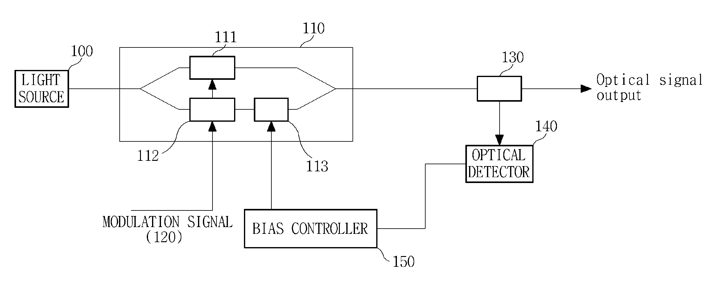
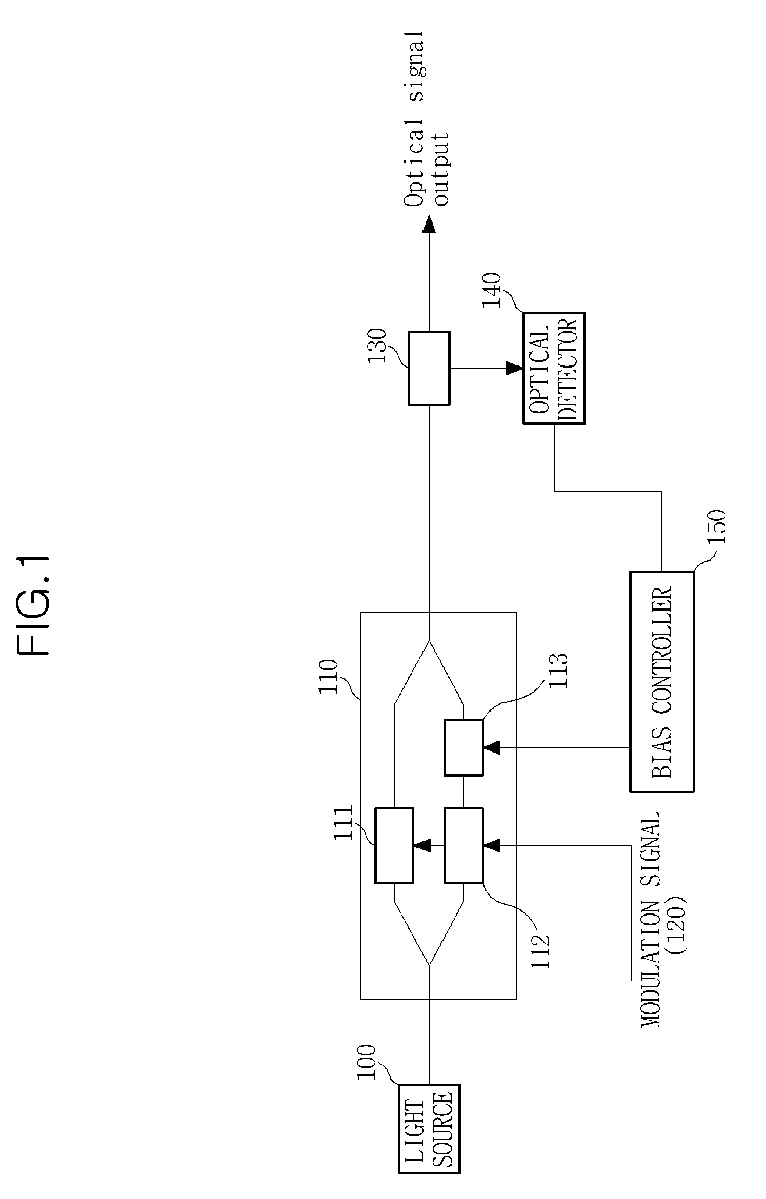
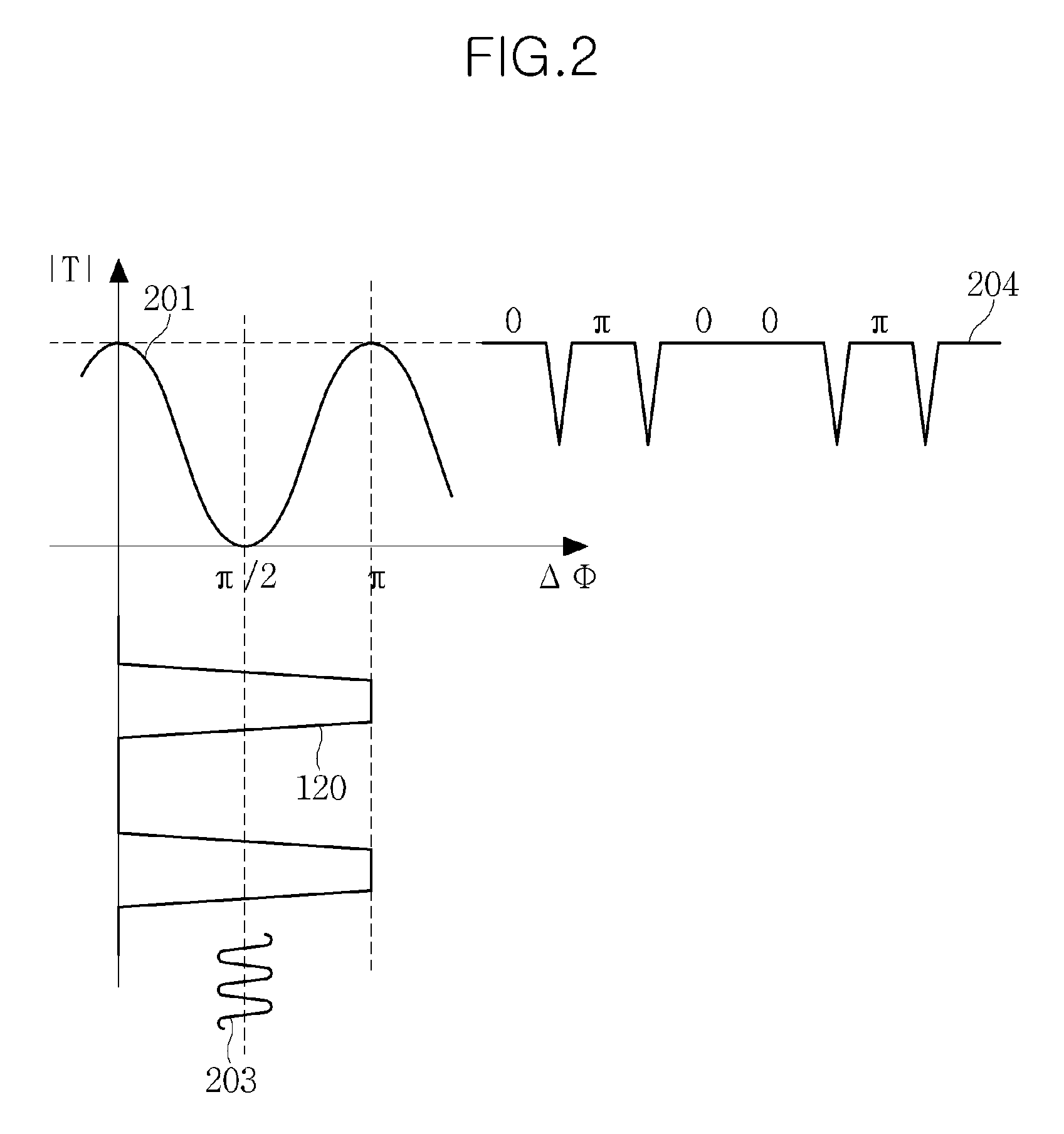
[0028]FIG. 1 is a configuration diagram of a binary phase shift keying (BPSK) optical transmission apparatus, and FIG. 2 is a diagram for explaining the principle of a BPSK optical modulator and bias dithering.

[0029]A light source 100 is configured to output an optical signal and may include a laser diode (LD). A BPSK modulator 110 receives the optical signal output from the light source 100, modulates the optical signal using a BPSK technique and outputs the modulated optical signal. The BPSK is one of phase shift keying (PSK) technique...


PUM

PropertyMeasurementUnit
opticalaaaaaaaaaa
frequenciesaaaaaaaaaa
optical signalaaaaaaaaaa

Abstract

An optical transmission apparatus for high-speed optical signal transmission is provided. The optical transmission apparatus includes an optical modulator which includes first and second modulators of a Mach-Zehnder (MZ) interferometer type which are connected in parallel, and an output stabilizer which controls biases for the first modulator, the second modulator and the optical modulator and stabilizes a final output optical signal of the optical modulator. The optical transmission apparatus can perform a stable optical signal output.

Description

CROSS-REFERENCE TO RELATED APPLICATIONS[0001]This application claims the benefit under 35 U.S.C. §119(a) of Korean Patent Application Nos. 10-2008-0124166, filed on Dec. 8, 2008, and 10-2009-0032189, filed on Apr. 14, 2009, the disclosures of both of which are incorporated herein in their entirety by reference for all purposes.BACKGROUND[0002]1. Field[0003]The following description relates to an optical transmission apparatus for high-speed optical signal transmission, and more particularly, to an optical transmission apparatus using a phase shift keying technique.[0004]2. Description of the Related Art[0005]Wavelength division multiplexing (WDM) is an optical transmission technique which substantially increases the transmission capacity of optical transmission networks. In the WDM technique, a plurality of wavelength channels are transmitted through one optical fiber. For example, if one wavelength channel has a transmission rate of 10 Gb / s, when 50 wavelengths are transmitted at t...

Claims


Application Information

Patent Timeline
Patent Type & Authority Applications(United States)
IPC IPC(8): H04B10/04H04B10/00H04B10/12
CPCH04B10/50575H04B10/5053
Inventor CHANG, SUN-HYOKCHUNG, HWAN-SEOKLEE, SANG-SOOKIM, KWANG-JOON
Owner ELECTRONICS & TELECOMM RES INST
Why Eureka
Try Eureka