Cold spray impact deposition system and coating process

a deposition system and spray spray technology, applied in the direction of liquid surface applicators, thin material processing, coatings, etc., can solve the problems of turbid flow of particulates, inefficient gas usage, and limited utility of each of these conventional techniques

Inactive Publication Date: 2010-06-10
US SEC THE ARMY THE
View PDF8 Cites 40 Cited by
  • Summary
  • Abstract
  • Description
  • Claims
  • Application Information

AI Technical Summary

Benefits of technology

[0006]A process for applying a ductile material spray coating on a substrate includes feeding a majority by atomic percent helium gas by a single path to a spray nozzle having a converging portion and a diverging terminal portion. In certain desirable embodiments, the inert gas forms a flow at a pressure of between about 2 and about 6 mega Pascal (MPa) incident on an inlet to the converging portion of the nozzle and at a temperature that is desirably less than about 30° Celsius. In certain desirable embodiments, a supply of ductile material particles having a mean x-y-z axially averaged linear dimension of between about 0.9 and about 95 microns is introduced into the nozzle and accelerated to a velocity of greater than about 500 meters per second upon exiting the nozzle. The accelerated particles impact the substrate to apply the ductile material spray coati

Problems solved by technology

Each of these conventional techniques has limited utility owing to attributes of each respective conventional deposition technique.
A problem associated with such a conventional system is turbid flow of particulate associated with the convergence of the

Method used


Image

  • Cold spray impact deposition system and coating process
  • Cold spray impact deposition system and coating process
  • Cold spray impact deposition system and coating process

Examples


example 1

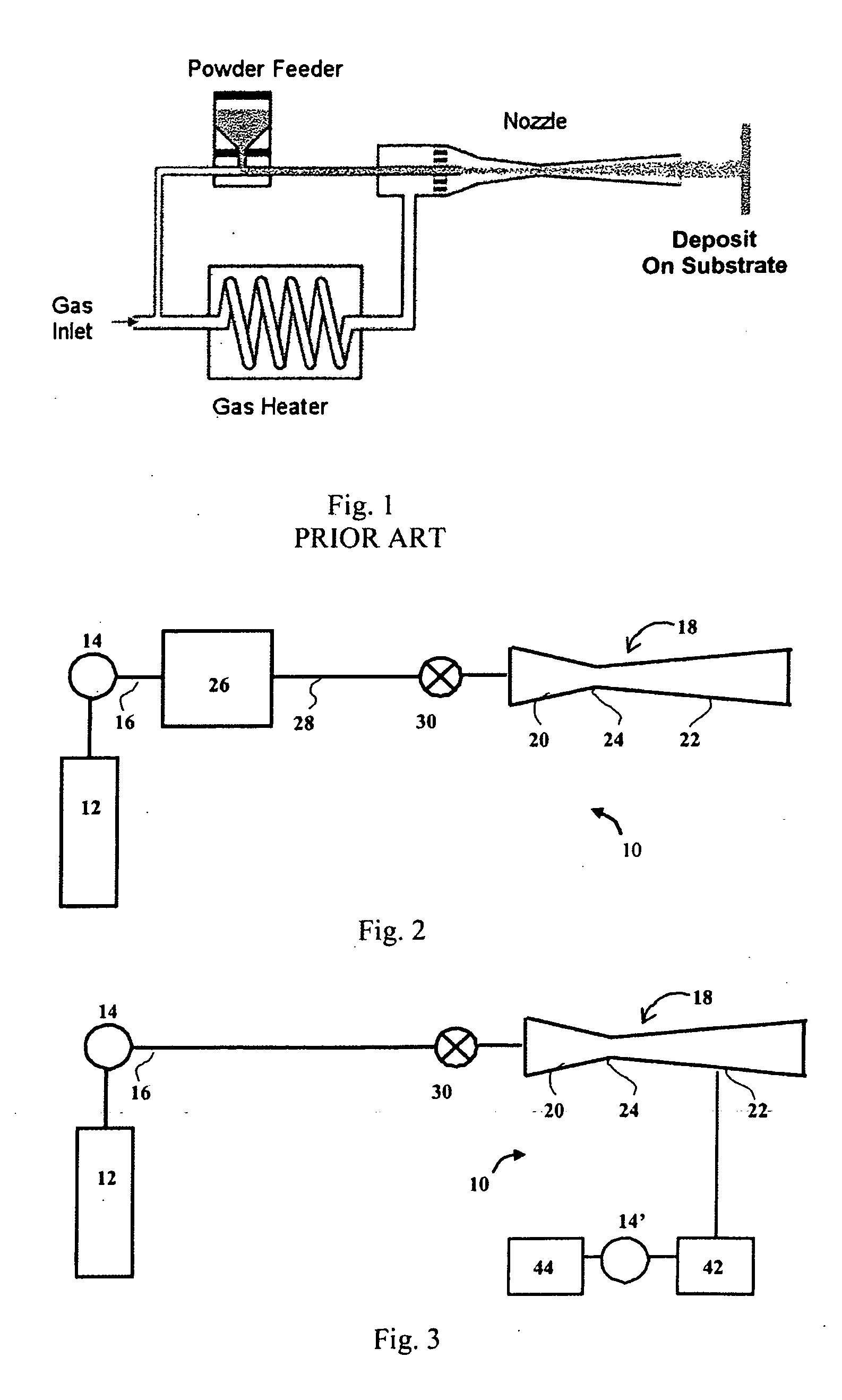
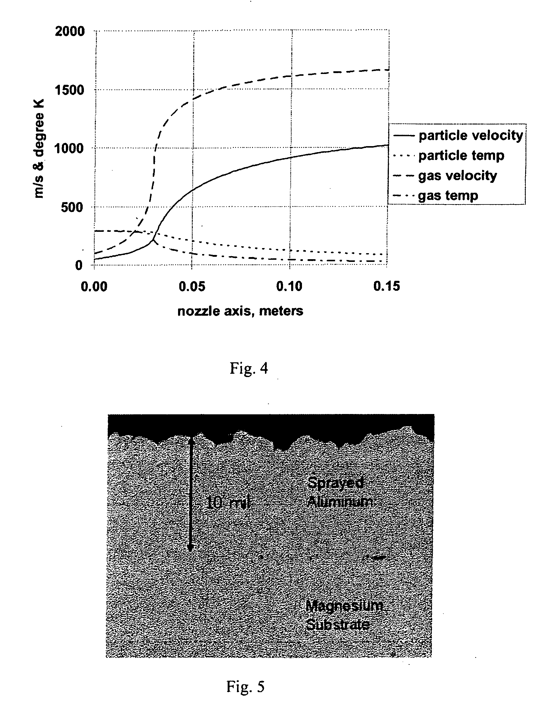
[0024]Using apparatus 10 of FIG. 2, pure helium gas in a K-type cylinder at an initial temperature of 20° Celsius and pressure of 2.8 MPa in the conduit 16 flows at 34 m3 / hour entrains spherical 20 micron-aluminum particles at a rate of 3 grams / minute exit the nozzle with sufficient velocity to achieve good impact plastic deformation on a magnesium substrate positioned 10 centimeters incident to the nozzle. The aluminum particles had a mean x-y-z axially averaged linear dimension of 20 micron. These depositions have also been successfully reproduced with aluminum (AlClad) and steel substrates. The calculated velocities and temperatures for the gas and the aluminum particles as a function of distance traveled through a nozzle is depicted in FIG. 4 for a nozzle having a converging portion with a 6.35 mm circular inlet that extends for 7.62 mm and then tapers over 6.35 mm to a minimal constriction of 1.0 mm and thereafter expanding smoothly to a terminal nozzle diverging circular cross...

example 2

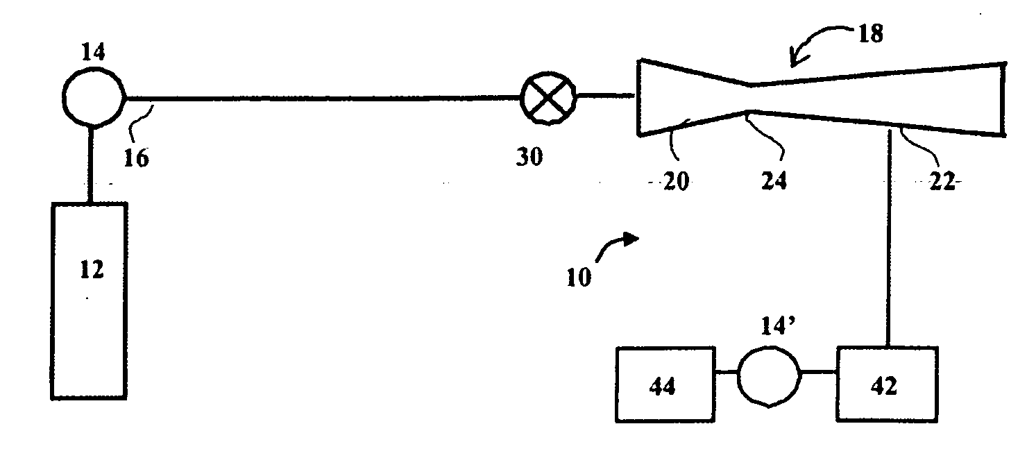
[0025]Using the apparatus of FIG. 3 with the same helium gas conditions and 20 micron spherical aluminum particles also fed at a rate of 3 grams per minute, with the exception that the 20 micron aluminum particles are now fed into the low pressure, divergent section, the calculated velocities and temperatures for the gas and the particles as a function of distance traveled through the nozzle is depicted in FIG. 6. The aluminum particles are noted to exit the nozzle at 900 meters per second and yield a coating similar to that depicted in FIG. 5 with respect to Example 1.


PUM

PropertyMeasurementUnit
Lengthaaaaaaaaaa
Lengthaaaaaaaaaa
Lengthaaaaaaaaaa

Abstract

A cold spray apparatus is provided that includes a nozzle having a converging section and a diverging terminal section. A gas supply meters a majority by atomic percent helium gas to the nozzle at an incident gas temperature of less than 30° Celsius and at an incident velocity of between 2 and 6 MPa. A particulate feeder provides ductile material particulate having a mean x-y-z axially averaged linear dimension of between 0.9 and 95 microns to the nozzle. A composition is also provided that includes a substrate and a coating of ductile metal. The coating has a void density of less than 1% by volume, and an average domain size of between 0.9 and 95 microns. The coating has a compressive residual stress.

Description

GOVERNMENT INTEREST[0001]The invention described herein may be manufactured, used, and licensed by or for the United States Government.FIELD OF THE INVENTION[0002]The present invention in general relates to an impact deposition system for depositing ductile particulate on a substrate at a temperature of less than 30° Celsius and in particular to a simplified carrier gas path to a system nozzle.BACKGROUND OF THE INVENTION[0003]There are numerous instances when an adherent metal coating is desired on a substrate. Such coatings are helpful in providing corrosion resistance and conductivity as illustrative modifications to a substrate. Conventional techniques for applying such coatings include sputter coating, electrochemical deposition and explosive welding. Each of these conventional techniques has limited utility owing to attributes of each respective conventional deposition technique. A more recent technique developed to address the shortcomings associated with other conventional de...

Claims


Application Information

Patent Timeline
IPC IPC(8): B32B5/02B05D1/12B05C19/04
CPCB05B7/1404Y10T428/25C23C24/04B05B7/1486
Inventor CHAMPAGNE, VICTOR KLEYMAN, PHILLIP F.HELFRITCH, DENNIS J.
Owner US SEC THE ARMY THE
Why Eureka
Try Eureka