Fuel cell system

Inactive Publication Date: 2010-06-10
HONDA MOTOR CO LTD
View PDF3 Cites 4 Cited by
  • Summary
  • Abstract
  • Description
  • Claims
  • Application Information

AI Technical Summary

Benefits of technology

[0016]The present invention can provide a simple and down-sized mechanism since the electrically driven valve-driving section of the present invention using the rotational driving source of an electric motor, uses a fewer number of parts than those of a pneumatic control system having a complex mechanism using many parts e.g. a regulator, a plurality of air-flow control valves, and air-switching valves for moving the discs. In addition, the present invention can provide a more power-saving fuel cell system since the cathode control unit stops supplying electricity to the motors used in the first and second shut-off valves locked in open state by the first and second valve lock units.
[0017]In the present invention, negative pressure produced in the cathode sealed by the cathode control unit may suck the first valve body of the first

Problems solved by technology

However, the prior art fuel cell system disclosed in Patent Document 2 has a disadvantage that power output efficiency may be reduced because the fuel cell system uses solenoid valves to which electricity must be supplied continuously while they are in open state.
In particular, the fuel cell has to bear more reduced power output efficiency if greater electricity is necessary for opening the solenoid valves.
The prior art of Patent Document 1, disclosing that each shut-off valve is switched by using air pressure (i.e. pneumatically) supplied from the buffer tank, may have another disadvantage that the shut-off valves, which must be opened during electro-chemical reaction in the fuel cell, may be closed

Method used


Image

  • Fuel cell system
  • Fuel cell system
  • Fuel cell system

Examples


Example

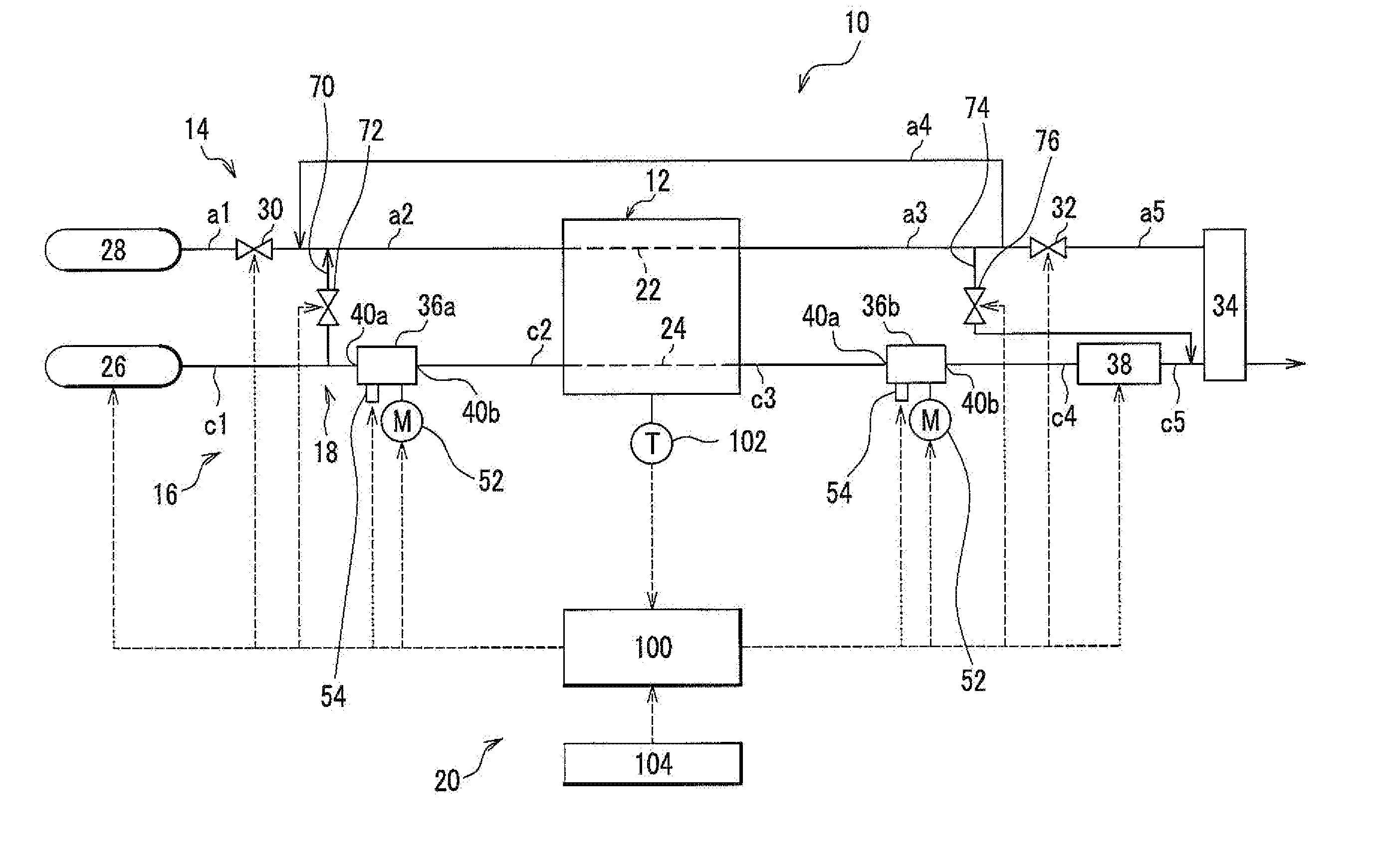
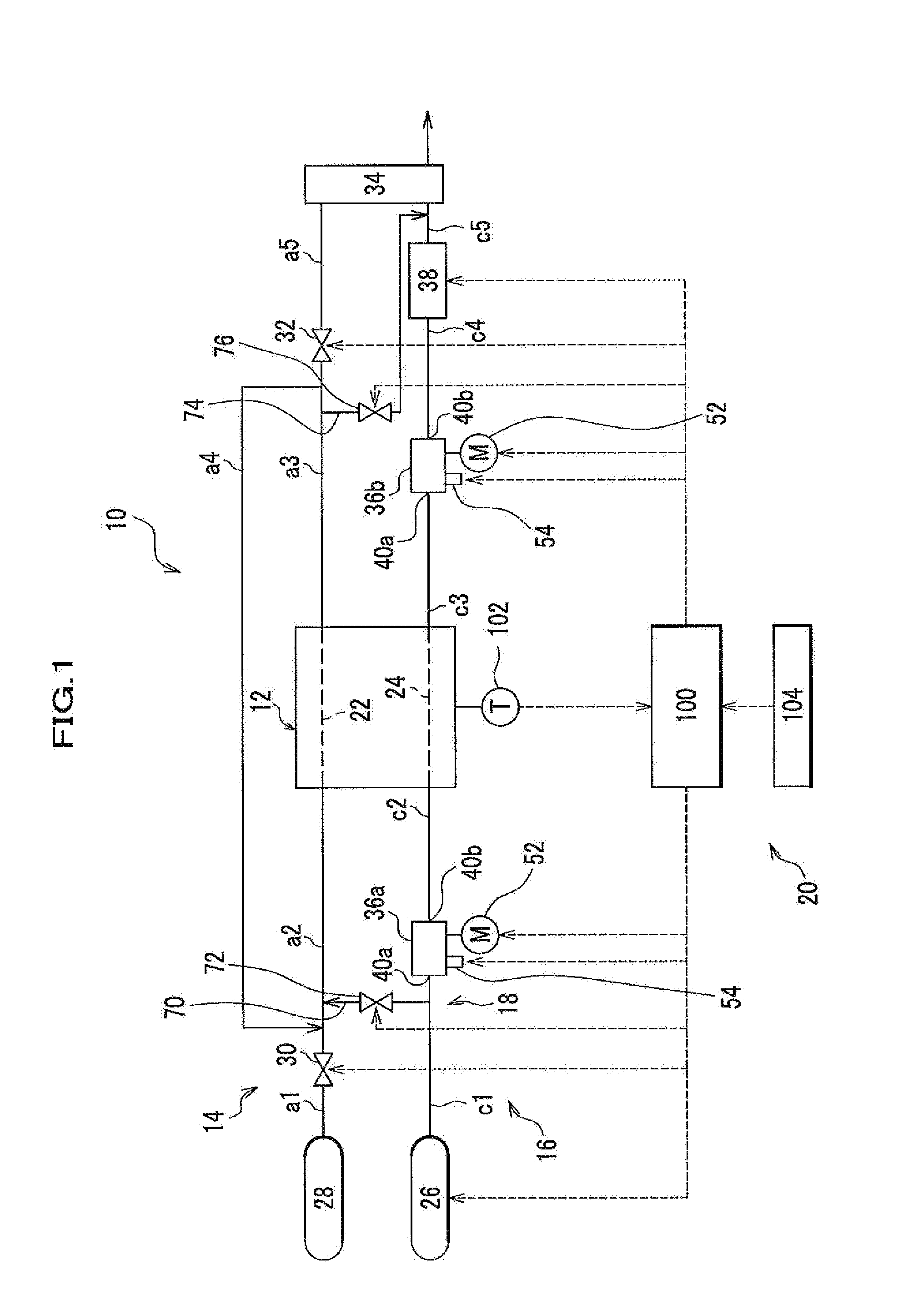
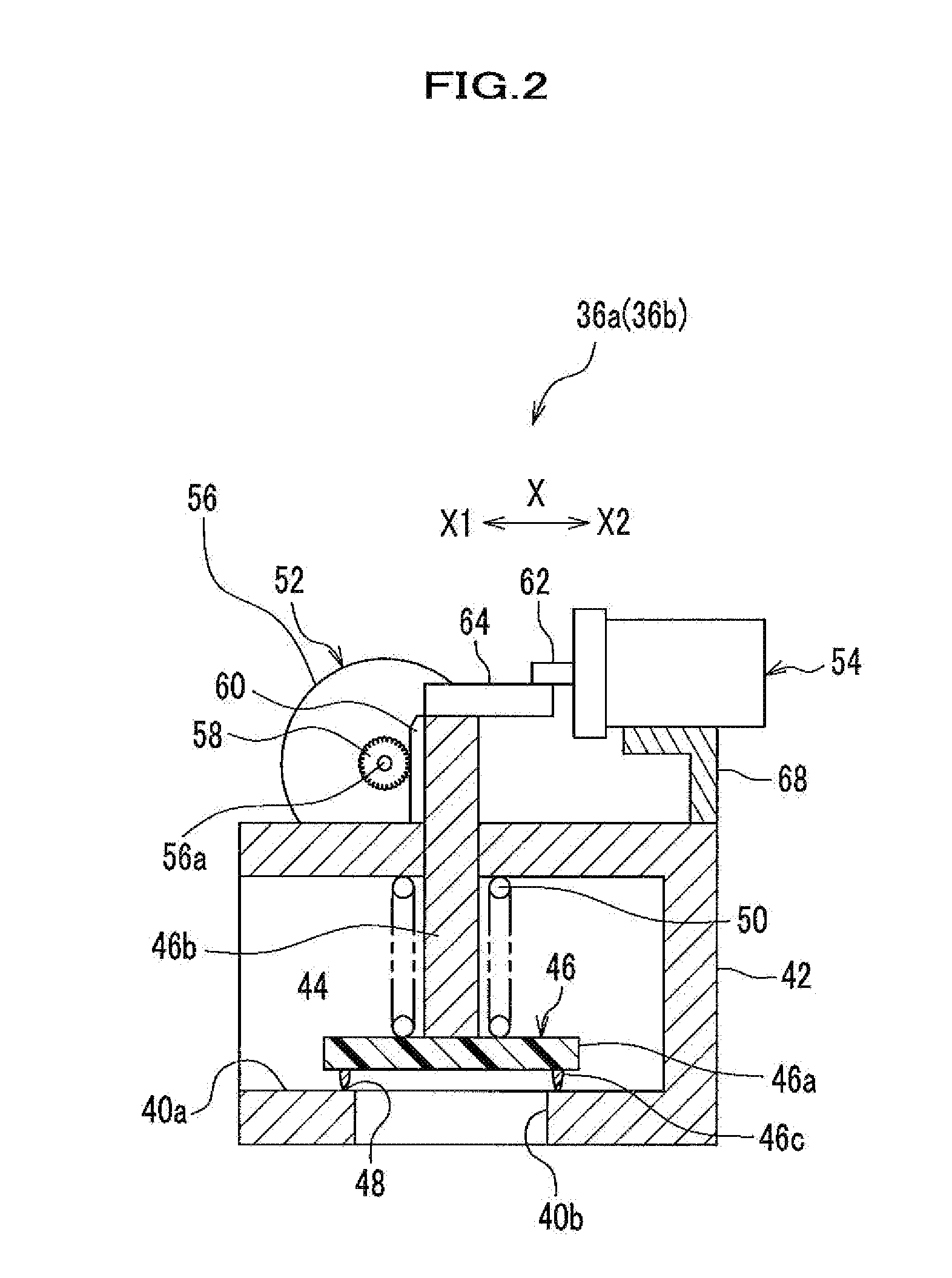
[0025]The structure of a fuel cell system according to an embodiment of the present invention will be explained in detail with reference to FIGS. 1 and 2. Although the embodiment explained herein relates to vehicles including fuel-cell vehicles, the present invention is not limited to fuel cells used in vehicles and can be applied to any other fuel cells used for transportation means including ocean vessels and aircrafts, and for stationary fuel cell systems.

[0026]As shown in FIG. 1, a fuel cell system 10 according to the present embodiment includes a fuel cell 12; an anode system 14; a cathode system 16; an anode-scavenging system 18; and a control system 20.

[0027]The fuel cell 12 is a polymer electrolyte fuel cell (PEFC) which includes a plurality of stacked single cells each having a membrane electrode assembly (MEA) placed between two separators (not shown in the drawings).

[0028]The MEA includes an electrolyte membrane (e.g. polymer membrane); a cathode; an anode; and the electr...


PUM


Abstract

A fuel cell system includes: a fuel cell; a normally-closed first shut-off valve provided upstream from the fuel cell and opening and closing pipes c1 and allowing air supplied from an air pump to pass therethrough; a normally-closed second shut-off valve opening and closing a pipe allowing cathode off-gas, discharged from the fuel cell, to pass therethrough; a valve-driving section for opening and closing discs of the shut-off valves; and valve lock units maintaining discs of the shut-off valves in open state when the cathode is released by opening the first shut-off valve and the second shut-off valve during electro-chemical reaction progressing in the fuel cell. This structure provides a simple and small-size fuel cell system capable of maintaining opening state of shut-off valves stably and reliably.

Description

CROSS REFERENCE TO RELATED APPLICATIONS[0001]This application claims the foreign priority benefit under Title 35, United States Code, §119 (a)-(d), of Japanese Patent Application No. 2008-310348, filed on Dec. 5, 2008, in the Japan Patent Office, the disclosure of which is herein incorporated by reference in its entirety.BACKGROUND OF THE INVENTION[0002]1. Field of the Invention[0003]The present invention relates to a fuel cell system capable of sealing a cathode by closing a first shut-off valve and a second shut-off valve after stopping electro-chemical reaction progressing in a fuel cell; and capable of releasing the cathode by opening the first shut-off valve and the second shut-off valve during the electro-chemical reaction progressing in the fuel cell.[0004]2. Description of the Related Art[0005]Japanese Patent Laid-open Publication No. 2008-218072 (hereinafter called Patent Document 1) discloses an example of fuel cell system including a fuel cell having an air-inlet shut-off...

Claims


Application Information

Patent Timeline
IPC IPC(8): H01M8/04
CPCH01M8/04201Y02E60/50H01M8/04223H01M8/04225H01M8/04228H01M8/04302H01M8/04303
Inventor TAKAGI, NARIHIROKASUYA, KURI
Owner HONDA MOTOR CO LTD
Why Eureka
Try Eureka