Battery and a Process for Making a Battery

a battery and process technology, applied in the field of batteries, can solve the problems of high cost and complex nature of cast-on strap machines, and achieve the effects of reducing the height of the battery, simplifying the process of invention, and facilitating incorporation

Inactive Publication Date: 2010-06-10
EH EURO GMBH
View PDF2 Cites 22 Cited by
  • Summary
  • Abstract
  • Description
  • Claims
  • Application Information

AI Technical Summary

Benefits of technology

[0043]The plate lugs may also be of any desired shape and size but are typically rectangular. The plate lugs are preferably somewhat longer than is conventional, in order that they extend to the part of the metal insert which is to be melted. The plate lugs may be at least 20 mm long, optionally at least 25 mm long, for example, at least 30 mm long. In conventional lead acid batteries, it is usual for the plate lugs to be short, for example, less than 20 mm long, in order to minimise the amount of material used and / or to minimise the overall height of the battery.
[0061]In the welding step of the process of the invention, heat will preferably be applied to the insert from outside the battery assembly, typically from above to melt an upper part of the insert. Preferably, the upper surface of the insert in the vicinity of the aperture or apertures is flat. Preferably, the insert or inserts are each fixed in a respective opening in the body of the lid and those openings are sized and shaped so that all of the plate lugs for a particular insert extend into the opening so that they can be welded from outside the battery assembly. It is also preferable for the opening in the body of the lid to be so sized and shaped that an exposed portion of the insert extends around all the plate lugs with a sufficient margin around the plate lugs to avoid burning the body of the lid during the welding.

Problems solved by technology

Cast-on strap machines are, however, typically both complex and costly and usually require further battery handling equipment before and after the cast-on strap machine to achieve the best production rates.

Method used


Image

  • Battery and a Process for Making a Battery
  • Battery and a Process for Making a Battery
  • Battery and a Process for Making a Battery

Examples


Embodiment Construction

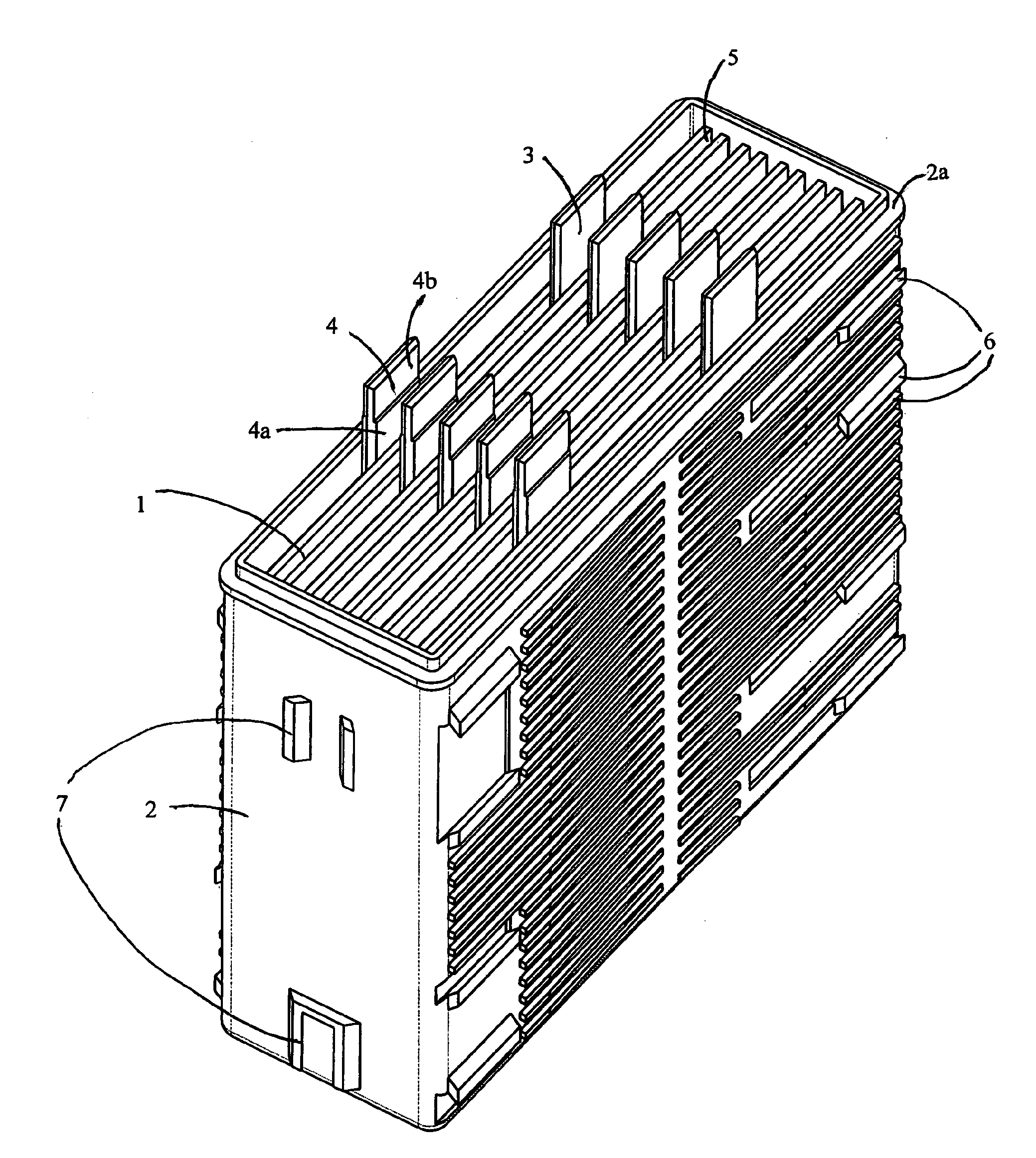
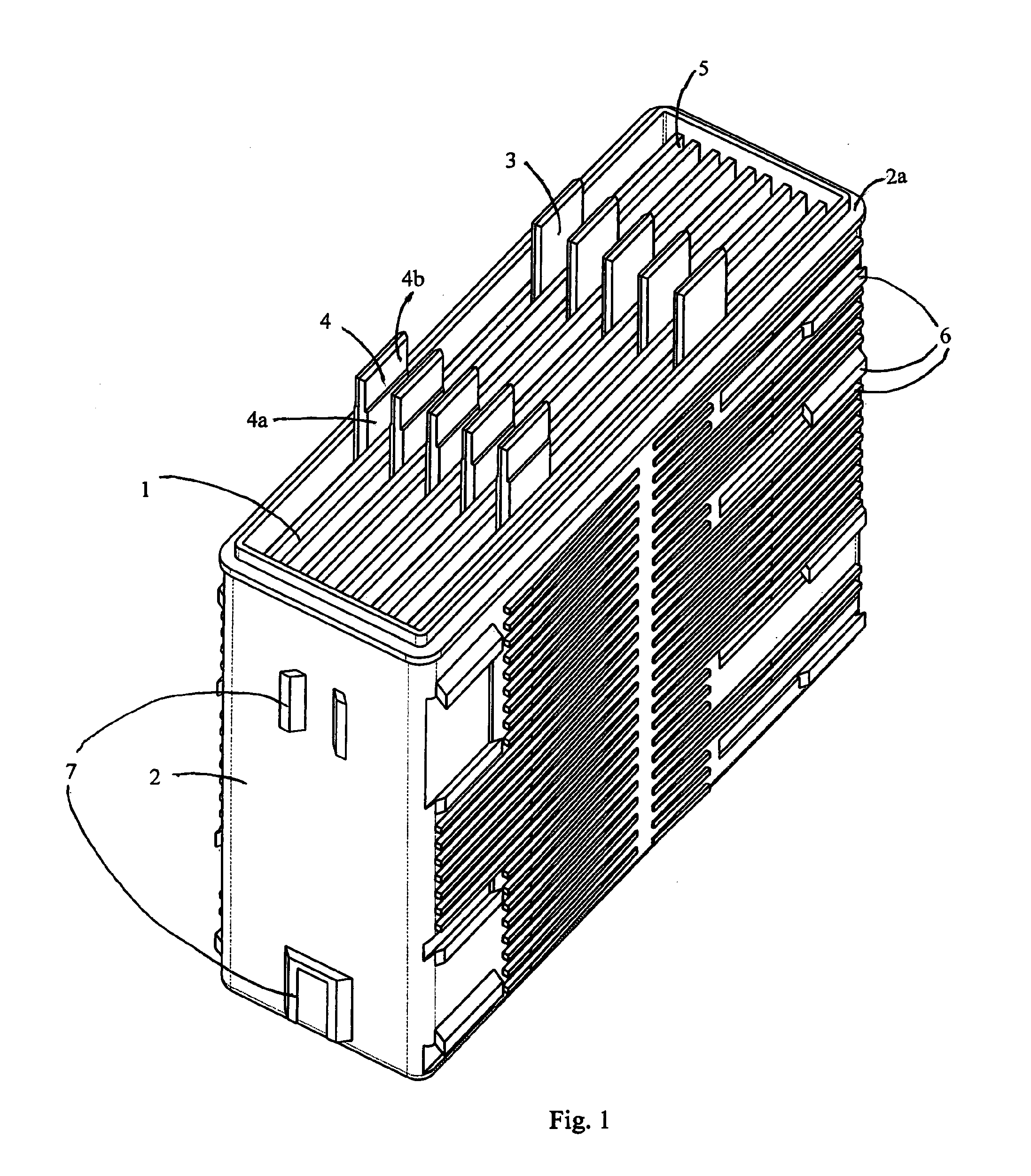
[0041]The process of the invention is especially suitable for the manufacture of lead acid batteries. Such batteries are used for a wide arrange of applications, including reserve power and motive power. In a preferred embodiment, the battery is a valve-regulated lead acid (VRLA) battery but the process of the invention is equally applicable to flooded cell batteries and motive power batteries.

[0042]The positive plates and negative plates may be any desired shape or size. The word “plate” refers to generally to any battery electrode. The invention is applicable to round cells, tubular batteries and bipolar batteries, as well as to batteries having conventional rectangular, flat plates.

[0043]The plate lugs may also be of any desired shape and size but are typically rectangular. The plate lugs are preferably somewhat longer than is conventional, in order that they extend to the part of the metal insert which is to be melted. The plate lugs may be at least 20 mm long, optionally at lea...


PUM

PropertyMeasurementUnit
depthaaaaaaaaaa
heightaaaaaaaaaa
voltageaaaaaaaaaa

Abstract

A process for making a battery includes providing a lid (31) having a least one metal insert (22) containing an aperture or apertures (26) for the plate lugs. During assembly of the battery the lid (31) is placed over the plate stack such that the plate lugs of the battery plates extend into the aperture or apertures (26). Heat is then applied to the outer surface of the metal insert (22) to weld the plate lugs to the insert (22).

Description

FIELD OF THE INVENTION[0001]The invention relates to a battery, especially a lead acid battery, and to a process of making batteries.BACKGROUND TO THE INVENTION[0002]Lead acid batteries typically comprise one or more cells with each cell having positive and negative plates separated by sheets of a porous insulating material. The manufacturing process for such batteries typically involves the following stages:[0003]1) The positive and negative plates and the separators are assembled as required to form a plate stack. Each plate has a plate lug and in the plate stack the lugs of the plates of each polarity align to form two rows.[0004]2) The plates of each polarity are connected together with a lead strap which runs along the respective row of lugs. The lead strap includes either a terminal post or a lead flag for connection to an adjacent cell.[0005]3) The plate stack is then inserted into a battery container.[0006]4) Where the battery includes more than one cell, and therefore has m...

Claims


Application Information

Patent Timeline
Patent Type & Authority Applications(United States)
IPC IPC(8): H01M2/02H01M6/00H01M50/541H01M50/147
CPCH01M2/043H01M2/1072H01M2/28H01M10/0413Y10T29/49108H01M10/14Y02E60/126Y10T29/4911H01M10/12Y02E60/10H01M50/147H01M50/541Y02P70/50
Inventor PARTINGTON, KENNETH MICHAELEVANS, RHODRI
Owner EH EURO GMBH
Why Eureka
Try Eureka