Crimping terminal

a crimping terminal and terminal technology, applied in the direction of contact members penetrating/cutting insulation/cable strands, connection contact member materials, contact effected by permanent deformation, etc., can solve the problem of ambiguity whether or not the crimping portion of the wire barrel is securely secured, the crimping force (compression ratio) is not strictly adjusted when crimped, and the crimping height is increased. the effect of reducing the compression ratio

Active Publication Date: 2010-06-10
YAZAKI CORP
View PDF6 Cites 19 Cited by
  • Summary
  • Abstract
  • Description
  • Claims
  • Application Information

AI Technical Summary

Benefits of technology

[0009]For achieving the above-described object, a crimping terminal according to claim 1 is a crimping terminal joined with an aluminum electric wire including a conductive core portion formed by a plurality of twisted core wires and a covered portion covering the conductive core portion, having: an insulation barrel crimped with the covered portion; a wire barrel crimped with the conductive core portion exposed by removing a predetermined length of the covered portion from an end of the aluminum electric wire; and a crimping portion formed at the wire barrel when the wire barrel is crimped to the conductive core portion of the aluminum electric wire, so as to form a conduct-purpose crimping portion and a wire-hold crimping portion at the crimping portion. The entire crimping portion or each of the conduct-purpose crimping portion and the wire-hold crimping portion is formed to a curved shape projecting upwardly or downwardly in a direction of moving a crimping die when viewing in a direction perpendicular both to the direction of moving the crimping die and a direction along a lengthwise of the aluminum electric wire so as to decrease a compression ratio and increase a crimp height toward the insulation barrel.

Problems solved by technology

Therefore, constriction resistance is generated when electric current flows only in a specific core wire, which may cause a blowout of the wire or continuity or contact failure.
However, since the inclination 11 of the above-described conventional art is formed straight, the crimping force (compression ratio) is not strictly adjusted when crimped.
Thus, it is ambiguous whether or not mechanical connection reliability of the crimping portion of the wire barrel is securely ensured.
In fact, the above-described conventional art retains a problem regarding to ensuring the secure mechanical connection of the crimping portion of the wire barrel.

Method used


Image

  • Crimping terminal
  • Crimping terminal
  • Crimping terminal

Examples


Embodiment Construction

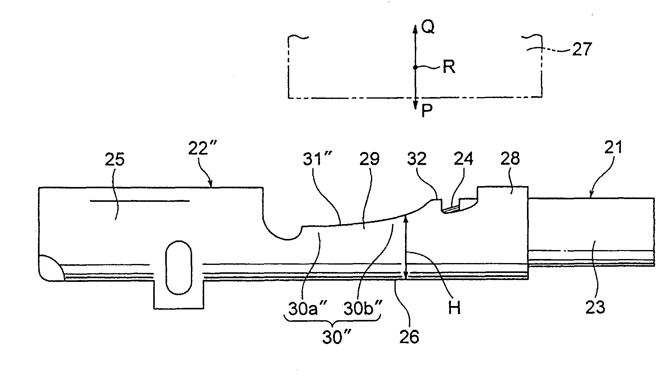
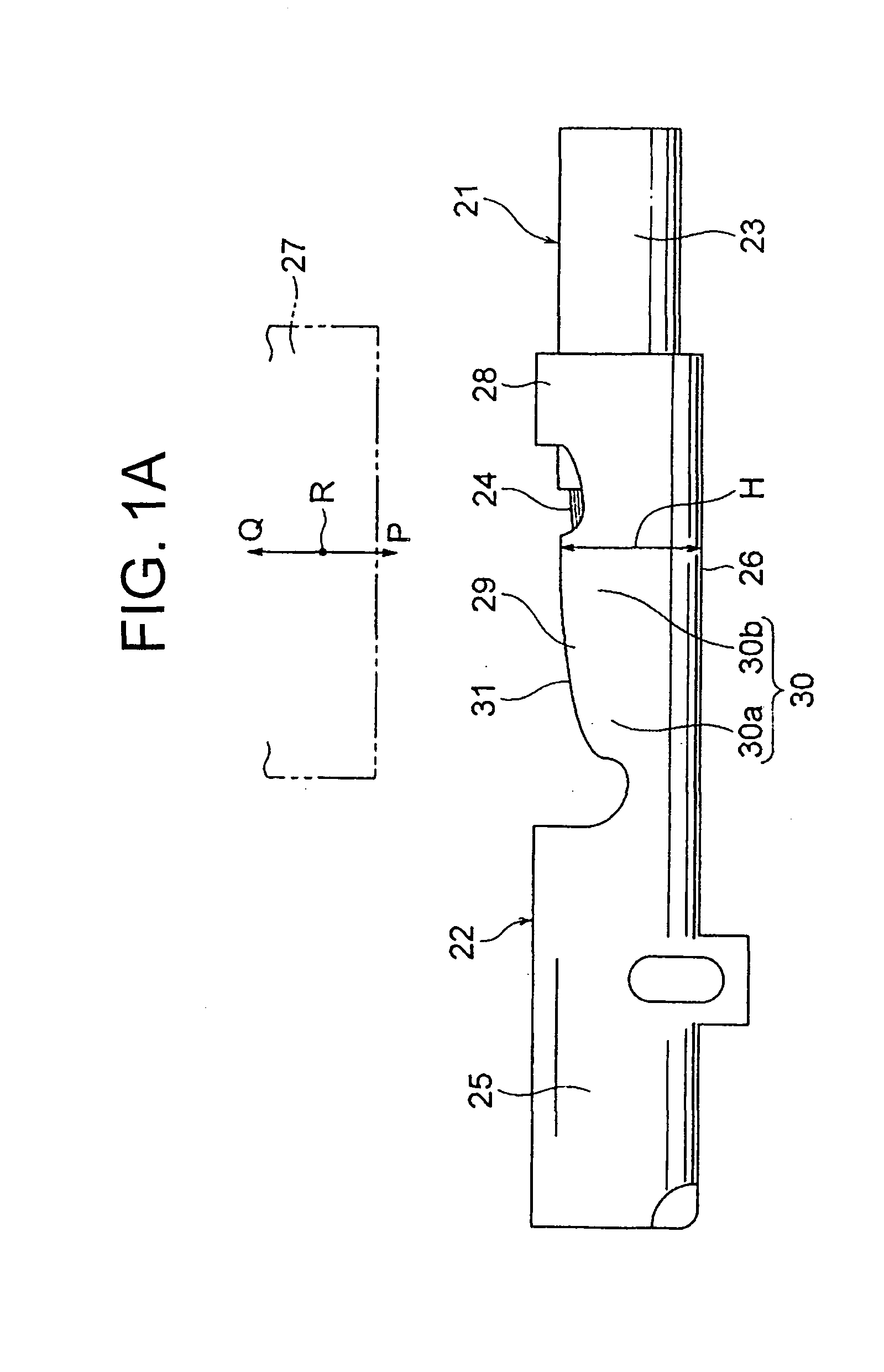
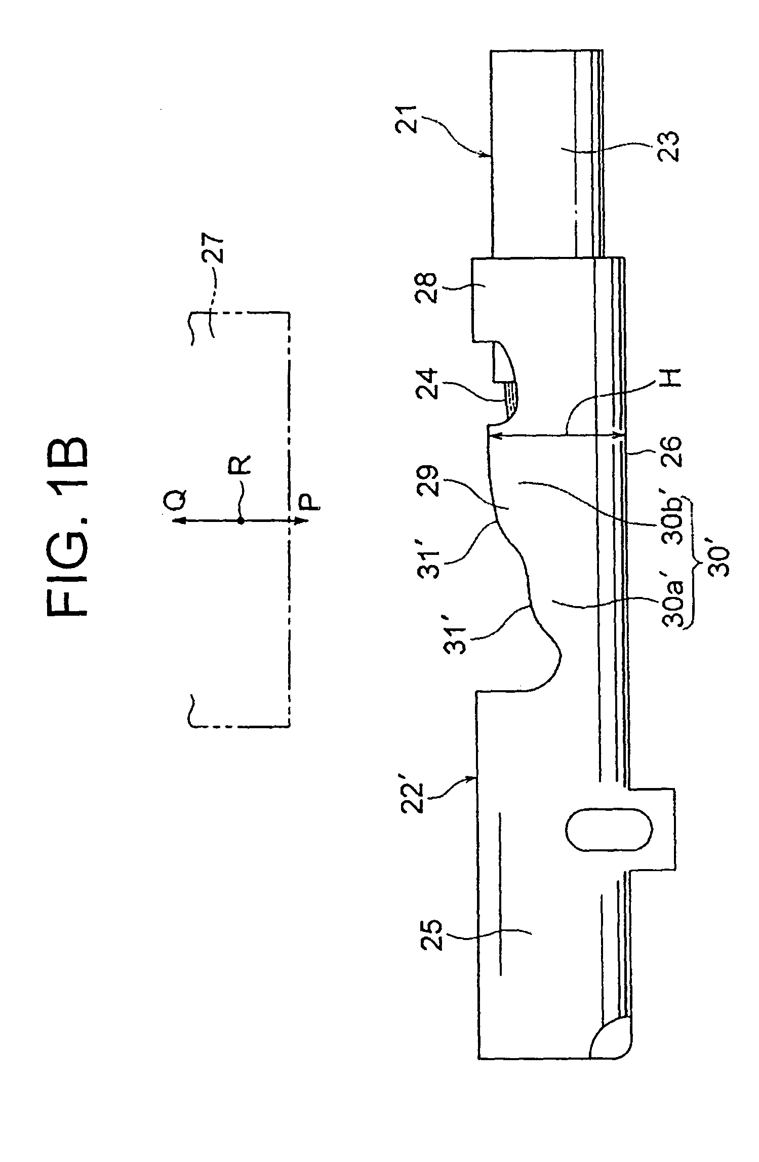
[0019]Embodiments of a crimping terminal according to the present invention will be explained hereinafter. FIG. 1A is a side view of a crimping terminal according to a first embodiment of the present invention and FIG. 1B is a side view of a crimping terminal according to a second embodiment of the present invention.

[0020]FIG. 1A shows an aluminum electric wire 21 and a crimping terminal 22. The aluminum electric wire 21, generally an aluminum wire or an aluminum alloy wire, has a plurality of twisted wires and a covered portion 23 covering the twisted wires. The aluminum wire 21 includes a conductive core portion 24 which is provided by removing a predetermined length of the covered portion 23 from an end of the aluminum wire 21. The conductive core portion 24 is provided at the twisted wires. The aluminum wire 21 is a known aluminum wire.

[0021]The crimping terminal 22 is manufactured by pressing a conductive metal plate, and is fixed to an end of the aluminum wire 21 by crimping. ...


PUM


Abstract

A crimping terminal joined with an aluminum electric wire, in which when the crimping terminal is crimped to the wire, a conduct-purpose crimping portion and a wire-hold crimping portion are formed at a crimping portion of a wire barrel of the crimping terminal. The crimping portion of the wire barrel is formed so as a curvature thereof is projected upwardly in a direction of moving a crimping die and so as a crimp height increases and a compression ratio decreases towards an insulation barrel of the crimping terminal. The curvature is shaped to have a constant degree of curvature, and is shaped to form a quadratic curve as a result of strictly adjusting a crimping force.

Description

BACKGROUND OF THE INVENTION[0001]1. Field of the Invention[0002]The present invention relates to a crimping terminal, especially a crimping form of the terminal for crimping a wire barrel of a crimping terminal to a conductive core portion of an aluminum electric wire (an aluminum electric wire or an aluminum alloy electric wire).[0003]2. Description of Related Art[0004]Recently, use of an aluminum electric wire has been demanded for weight reduction and recycling purposes for an automobile and such. Compared to a conventional copper electric wire, the aluminum electric wire has lower mechanical strength and lower meltdown temperature. Also oxidization of the surface thereof is easily produced on respective twisted core wires constituting the aluminum electric wire. Therefore, constriction resistance is generated when electric current flows only in a specific core wire, which may cause a blowout of the wire or continuity or contact failure.[0005]Japanese Patent Publication No. 2005-...

Claims


Application Information

Patent Timeline
Patent Type & Authority Applications(United States)
IPC IPC(8): H01R4/24
CPCH01R4/62H01R4/185
Inventor WATANABE, JINAOKI, YOSHIHITO
Owner YAZAKI CORP
Why Eureka
Try Eureka