Graft Fixation

Inactive Publication Date: 2010-06-10
SMITH & NEPHEW INC
View PDF99 Cites 45 Cited by
  • Summary
  • Abstract
  • Description
  • Claims
  • Application Information

AI Technical Summary

Benefits of technology

[0013]In an embodiment, the present disclosure relates to a method of fixating tissue grafts to bone. The method includes providing at least two tissue grafts; coupling the at least two tissue grafts; inserting the at least two tissue grafts into a

Problems solved by technology

The use of a fastener, such as an interference screw, may create complications for several reasons: the possibility of the screw threads damaging the grafts during screw installation if the screw is too big in relation to the graft and/or if the space between the passage and the grafts is too small, the graft rotating with

Method used


Image

  • Graft Fixation
  • Graft Fixation
  • Graft Fixation

Examples


Example

EXAMPLE

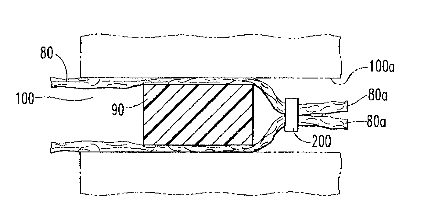
[0046]An 8.5 mm hole was drilled through the centre of a block of 20 pcf sawbone having the following dimensions: 42 mm long, 31 mm wide, and 31 mm thick.

[0047]Two pieces of 7 inch long 125 lb braided nylon rope were doubled over and inserted into the hole so that the four ends of rope passed all the way through the hole in the sawbone. An anchor including Poly (D,L lactide-co-glycolide) and calcium carbonate was inserted into the hole ensuring that the strands of nylon rope passing through the hole did not cross over one another and each of the four ends of nylon had its own quadrant of the hole. The anchor was processed via a die drawing process to include shape memory qualities. The ratio of lactide:glyeolidc was 85:15 and the calcium carbonate was present at between about 35.5% by weight of the polymer composition. Once in place, the plug was relaxed by immersion of the block, plug, and rope into hot water (approximately 80° C. for 5 min). When the block containing the pl...


PUM


Abstract

The present disclosure relates to an anchor for fixating a tissue graft to bone. The anchor includes a through hole extending an entire length of the anchor and a polymer composition having shape memory qualities. Other anchors and methods for fixating a tissue graft to bone are also disclosed.

Description

CROSS-REFERENCE TO RELATED APPLICATIONS[0001]This application is a U.S. National Stage Application, submitted under 35 U.S.C. 371, claiming priority to PCT International Patent Application PCT / US2008 / 060401 filed on Apr. 16, 2008, which claims priority to U.S. Patent Application No. 60 / 912,828 filed on Apr. 19, 2007, the disclosures of which are incorporated herein by reference in their entirety.BACKGROUND[0002]1. Field of the Invention[0003]The present disclosure relates generally to tissue graft fixation and, more particularly, to tissue graft fixation via the use of shape memory polymer material.[0004]2. Related Art[0005]A ligament, such as an anterior cruciate ligament (ACL), that has ruptured and is non-repairable, is generally replaced arthroscopically by a tissue graft. The tissue graft may be harvested from a portion of a patellar tendon having so called “bone blocks” at each end, and from the semitendonosis and gracilis. Alternatively, the tissue graft can be funned from sy...

Claims


Application Information

Patent Timeline
IPC IPC(8): A61F2/08
CPCA61B2017/00004A61B2017/00871A61F2/0811A61F2002/0852A61F2002/0858A61L2400/16A61F2002/0888A61F2210/0014A61L27/14A61L27/50A61F2002/0864
Inventor MONTES DE OCA BALDERAS, HORACIOBROWN, MALCOLMHOWLING, GRAEMEFENWICK, STEVECOTTON, NICHOLASBRUMFIELD, DAVID
Owner SMITH & NEPHEW INC
Why Eureka
Try Eureka