Tool stocker, machine tool system, and tool damage detecting apparatus

a technology of tool damage detection and tool stocking, which is applied in the direction of attachable milling devices, manufacturing tools, instruments, etc., can solve the problems of lowering the accuracy with which workpieces can be machined, over-operations of tool transfer, and tool transfer failure, so as to achieve the effect of easily and stably transferring tools

Active Publication Date: 2010-06-10
HONDA MOTOR CO LTD
View PDF11 Cites 67 Cited by
  • Summary
  • Abstract
  • Description
  • Claims
  • Application Information

AI Technical Summary

Benefits of technology

[0015]A general object of the present invention is to provide a ...

Problems solved by technology

However, the machine tool system needs to have a sufficiently large tool stocker and a sufficiently large number of stored tools.
The above operations for transferring the tool are complex, and involve turning of the tool.
Therefore, such operations tend to cause a tool transfer failure, due to positional misalignments between the tool stockers and a tool gripper of the main spindle, as well as dislodgment of the tool from the turn arm.
Since the tool is turned by the turn arm, it is likely to cause the machine tool to wobb...

Method used


Image

  • Tool stocker, machine tool system, and tool damage detecting apparatus
  • Tool stocker, machine tool system, and tool damage detecting apparatus
  • Tool stocker, machine tool system, and tool damage detecting apparatus

Examples


first embodiment

[0096]Initially, the present invention will be described below.

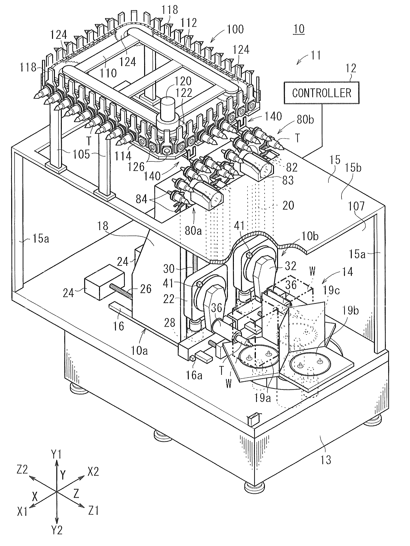
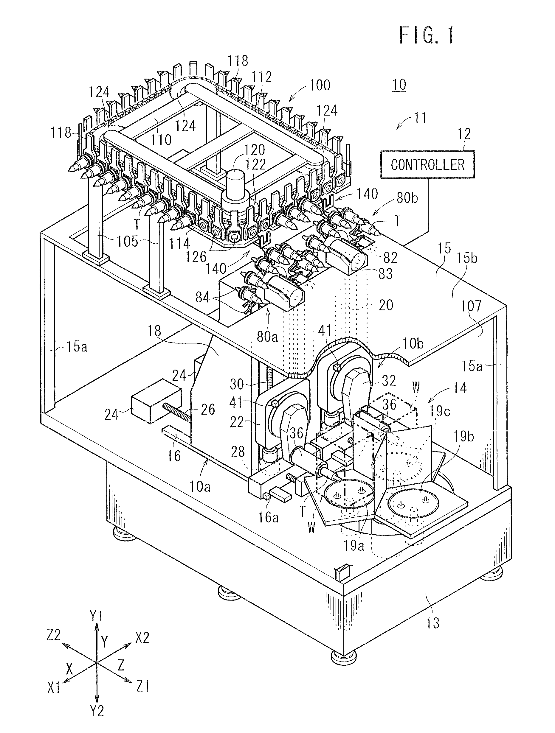
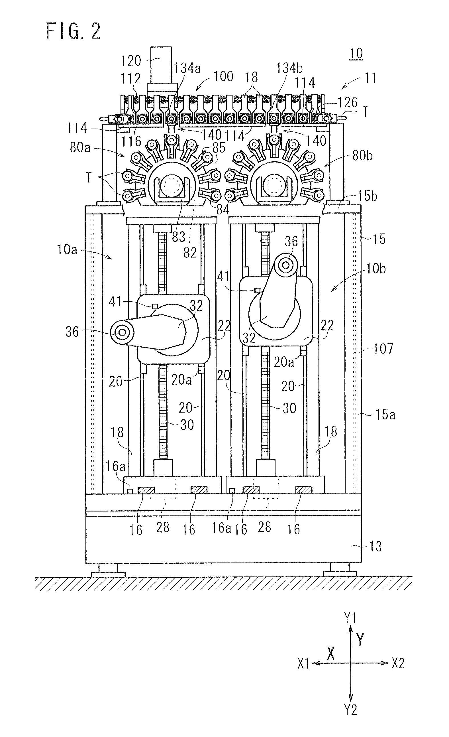
[0097]FIG. 1 is a perspective view, partially cut away, of a machine tool system 10 incorporating a tool stocker 11 therein according to the first embodiment. FIG. 2 is a front elevational view of the machine tool system 10 shown in FIG. 1, and FIG. 3 is a side elevational view of the machine tool system 10 shown in FIG. 1. The machine tool system 10 operates to machine workpieces W by drilling, boring, honing, etc. In order to define respective orientations of the machine tool system 10, the horizontal directions in FIG. 2 are referred to as X directions (X1, X2 directions), the vertical directions as Y directions (Y1, Y2 directions), and the depthwise directions perpendicular to the X and Y directions as Z directions (Z1, Z2 directions) (see FIG. 3). The X and Y directions refer to respective directions in a plane, which are perpendicular to each other.

[0098]The machine tool system 10 comprises a first machine tool 10a...

second embodiment

[0176]the present invention will be described below.

[0177]FIG. 23 is a perspective view, partially cut away, of a machine tool system 101 incorporating therein a tool damage detecting apparatus according to the second embodiment of the present invention. Those components of the machine tool system 101 which are identical in structure, function, and advantage to those of the machine tool system 10 according to the first embodiment are denoted using identical reference characters, and such components will not be described in detail below.

[0178]As shown in FIG. 23, the machine tool system 101 does not include the auxiliary stocker 100 of the machine tool system 10 shown in FIG. 1, and includes a tool damage detecting apparatus 200, which is disposed between the two main stockers (tool stockers, tool magazines) 80a, 80b. The machine tool system 101 may incorporate additional components, apart from the tool damage detecting apparatus 200, which are identical to those of the machine tool ...


PUM

PropertyMeasurementUnit
Lengthaaaaaaaaaa

Abstract

A tool stocker includes main stockers for holding a plurality of tools detachably mounted on a main spindle for machining a workpiece, an auxiliary stocker for holding and transferring tools to and from the main stockers, and a tool transfer mechanism for transferring tools between the main stockers and the auxiliary stocker. The auxiliary stocker includes a plurality of tool pods for removably supporting the tools therein, a rail in sliding engagement with outer surfaces of the tool pods, a chain for moving the tool pods in sliding engagement with the rail, and a motor for actuating the chain. The rail has a recess defined therein in alignment with the tool transfer mechanism, such that the tools transferred by the tool transfer mechanism pass through the recess.

Description

CROSS-REFERENCE TO RELATED APPLICATION[0001]This application is based upon and claims the benefit of priority from Japanese Patent Applications No. 2008-310156 filed on Dec. 4, 2008, No. 2008-310164 filed on Dec. 4, 2008 and No. 2008-311082 filed on Dec. 5, 2008, of which the contents are incorporated herein by reference.BACKGROUND OF THE INVENTION[0002]1. Field of the Invention[0003]The present invention relates to a tool stocker for holding and storing a plurality of tools that can detachably be mounted on a main spindle for machining a workpiece, a therein, and a tool damage detecting apparatus for use in a machine tool system.[0004]2. Description of the Related Art[0005]Generally, machine tool systems have been used in the art, which have a tool stocker for holding and storing a plurality of detachable tools, and which machine a workpiece in various machining modes with tools selected from the tool stocker, wherein the tools are replaceably mounted on a main spindle. Such machin...

Claims


Application Information

Patent Timeline
IPC IPC(8): G06F19/00
CPCY10T29/5196Y10T483/1891B23Q17/22Y10T483/1795B23Q3/15773Y10T409/30392Y10T483/179Y10T483/136B23Q3/15733Y10T483/115B23Q2039/002Y10T409/309464Y10T409/307616Y10T409/307168Y10T483/175Y10T483/1827Y10T483/1855Y10T483/1882Y10T483/1864B23Q3/15539
Inventor UCHIKAWA, MOTOKISHIBATA, SHOJISHIBATA, TAKESHIARAKAWA, SHUGOKUBO, MASAKAZUTANAKA, TATSUHIKOMASUDA, KENICHI
Owner HONDA MOTOR CO LTD
Why Eureka
Try Eureka