
a mobile air cushion

An air cushion and cushion body technology, applied in the field of mattresses, can solve the problems of reducing the friction coefficient, unable to move easily, and unfavorable for the stable and effective work of the air cushion, so as to achieve the effects of improving stability and effectiveness, and improving energy saving and quickness.

Active Publication Date: 2022-02-22
泗县微腾知识产权运营有限公司
View PDF11 Cites 0 Cited by
  • Summary
  • Abstract
  • Description
  • Claims
  • Application Information

AI Technical Summary

Problems solved by technology

[0004] Although the air cushion in the above-mentioned technology has the advantages of good air tightness, effective reduction of friction coefficient, convenient portability, convenient inflation, and cleanliness, when the patient is heavy, the ordinary air cushion cannot be used because of the limited exhaust at the bottom. Provide sufficient buoyancy, so that the air cushion cannot move easily due to the high friction coefficient of the lower surface. At the same time, because the vent hole at the bottom of the air cushion is in a normally open state, when the air cushion is just started or after use, the inside of the air cushion Part of the gas will flow out from the vent hole. In order to make the air cushion work effectively or effectively support the patient, it is necessary to use the air pump to continuously inflate the air cushion with high intensity, resulting in waste of gas and electricity inside the air cushion. , and it is not conducive to the stable and effective work of the air cushion

Method used


Image

  • a mobile air cushion
  • a mobile air cushion
  • a mobile air cushion

Examples


Embodiment approach

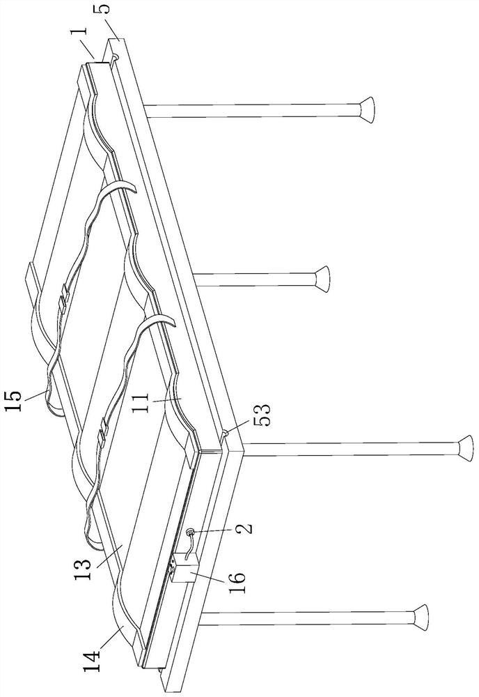
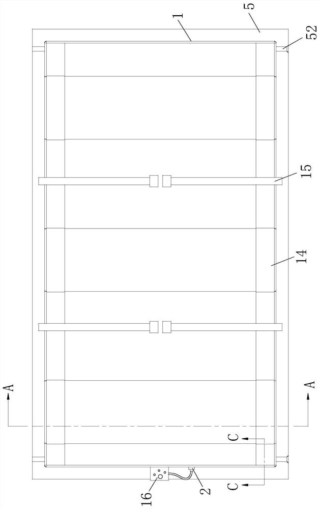
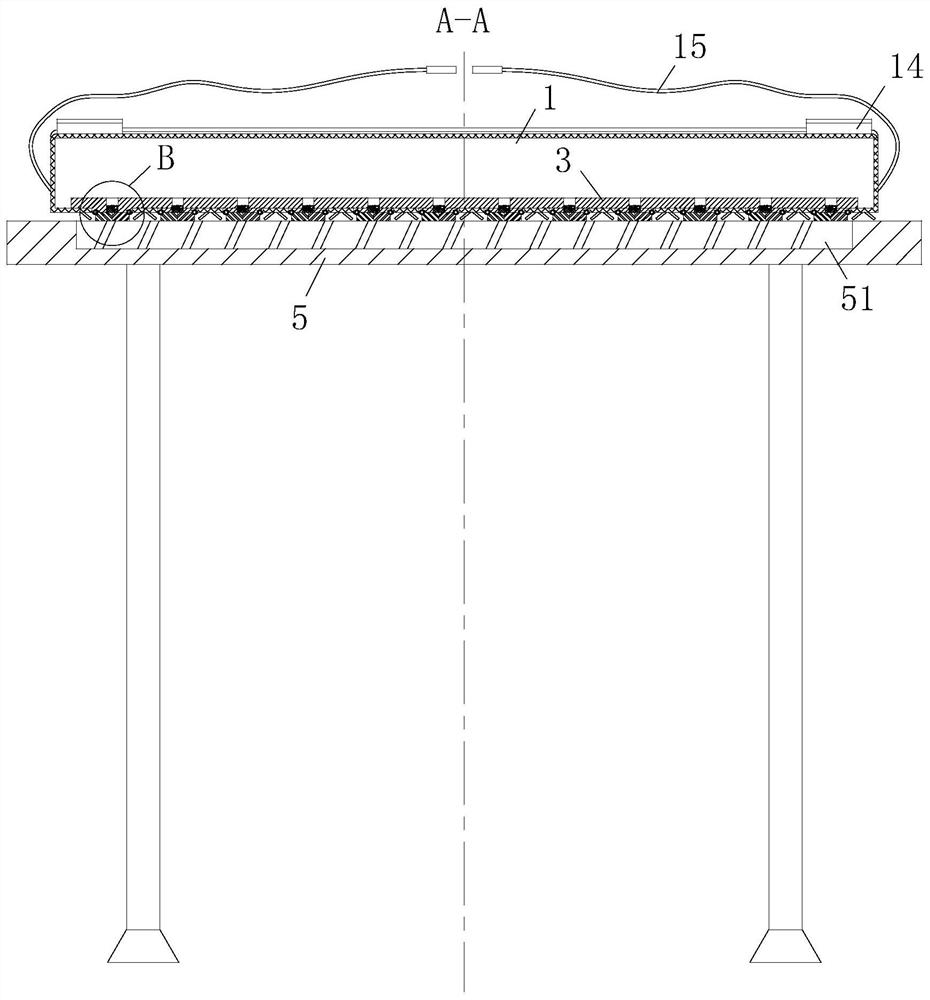
[0029] As an embodiment of the present invention, an inclined limiting plate 6 is connected to the bottom surface of the pad body 1 on one side of the blocking plate 4, and the bottom end of the limiting plate 6 can carry out Resist and limit the rotation angle of the blocking plate 4; during work, when the electromagnet 51 attracts the blocking plate 4, the free end of the blocking plate 4 is easily rotated to the same position under the action of the electromagnet 51. The bed boards 5 fit each other, so that the cushion body 1 can easily drive the blocking board 4 to be stuck at the position where the two bed boards 5 are handed over during the process of transferring to another bed board 5 . The limit plate 6 whose rotation angle is limited, so that when the block plate 4 moves to fit with the end of the limit plate 6, there is a certain gap between the free end of the block plate 4 and the bed board 5 , not only reduce the jamming of the blocking board 4 when it is transfe...


PUM


Abstract

The invention belongs to the technical field of mattresses, and specifically relates to a mobile air cushion, which includes a cushion body, an exhaust hole is opened on the bottom surface of the cushion body, an air pump is installed at the end of the cushion body, and an air pump is installed at the end of the cushion body. An inflating nozzle connected to the air pump is provided on the upper part, and a suspension board is pasted on the inner bottom surface of the pad body, and an extension part and a through hole are respectively provided at the position corresponding to the suspension board and the exhaust hole, and the bottom of the extension part The end is rotatably connected with a blocking plate, the side free end of the blocking plate is connected with a blocking block, the bottom of the pad body is provided with a bed board, and an electromagnet is installed in the bed board; The board and the sealing structure are set at the vent hole, which makes the cushion body more relaxed and stable during the transfer process, reduces the difficulty of transferring the patient due to the heavy body size, and reduces the gas inside the cushion body from being released when the air cushion is not working. The loss of the vent hole improves the energy saving and quickness of the cushion body during use.

Description

technical field [0001] The invention belongs to the technical field of mattresses, in particular to a mobile air mattress. Background technique [0002] In the existing medical industry field, the medical air mattress can help the patient's skin become necrotic due to local pressure for a long time, and can effectively reduce the occurrence of bedsores. When bedridden patients need to transfer or change beds after surgery or during surgery, they need to cooperate with sliding pads to lift and transfer. For patients who are usually bedridden, it can help the patient's skin breathe and reduce cell necrosis caused by local pressure. In the prior art, there is an inflatable sliding pad, the bottom of which is provided with vent holes, so that when the gas is discharged from the vent holes, a certain buoyancy can be generated, and the friction coefficient of the bottom of the inflatable sliding pad is reduced, thereby reducing the difficulty of lifting and transferring. Since th...

Claims


Application Information

Patent Timeline
Patent Type & Authority Patents(China)
IPC IPC(8): A61G7/05A61G7/14
CPCA61G7/05A61G7/1026A61G7/1055
Inventor 胡坤许凯
Owner 泗县微腾知识产权运营有限公司
Learn More