
Choked Flow Isolator for Noise Reduction in Analytical Systems

a technology of noise reduction and isolator, which is applied in the direction of separation of dispersed particles, instruments, separation processes, etc., can solve the problems of sensitivity of detectors to “noise” and the change of the room containing the chromatograph

Active Publication Date: 2010-06-17
AGILENT TECH INC
View PDF4 Cites 27 Cited by
  • Summary
  • Abstract
  • Description
  • Claims
  • Application Information

AI Technical Summary

Problems solved by technology

As the sensitivity of the detectors has improved, the sensitivity of the detectors to “noise” resulting from intermittent pressure changes in the room containing the chromatograph has become a problem.

Method used


Image

  • Choked Flow Isolator for Noise Reduction in Analytical Systems
  • Choked Flow Isolator for Noise Reduction in Analytical Systems
  • Choked Flow Isolator for Noise Reduction in Analytical Systems

Examples


Embodiment Construction

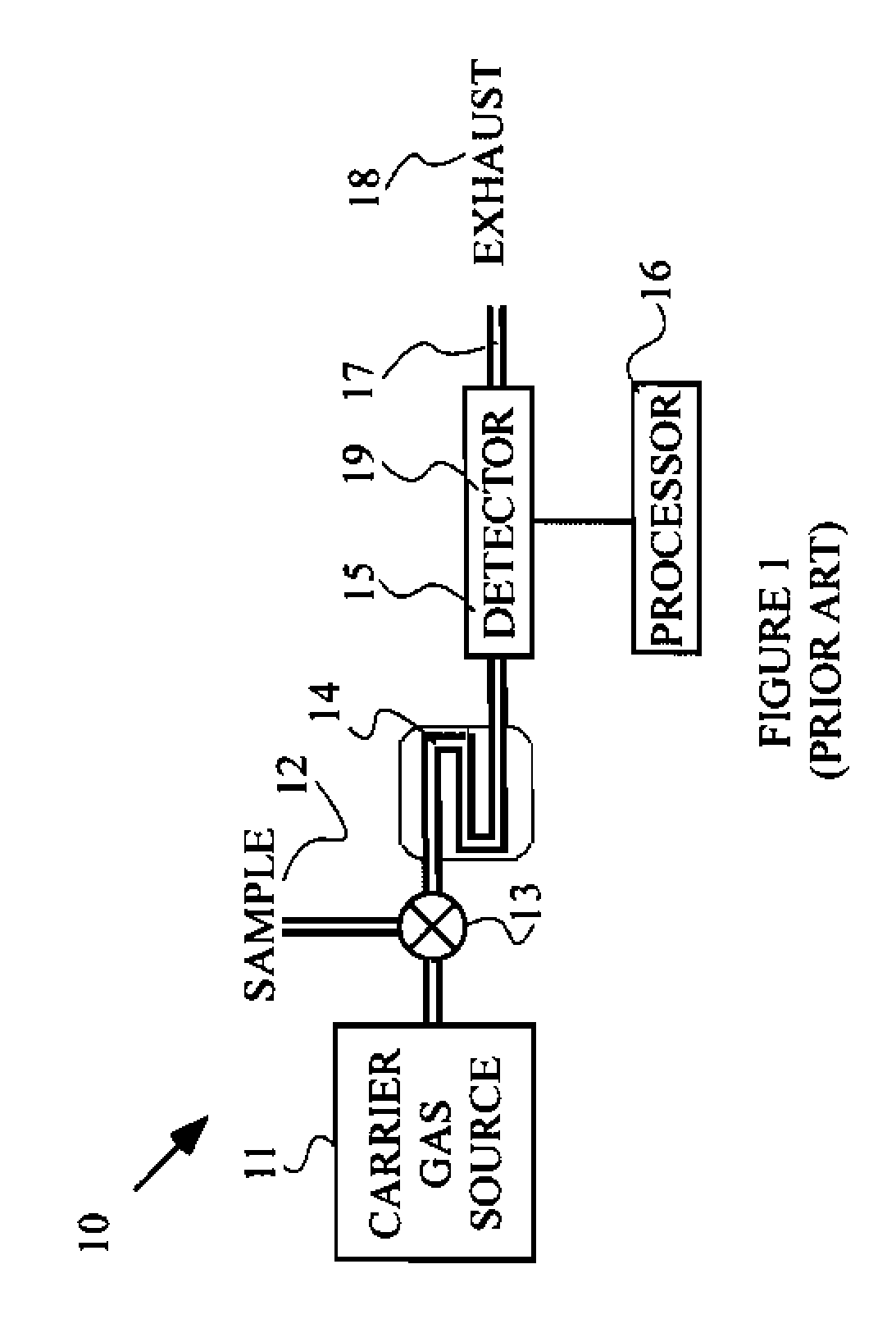
[0008]The manner in which the present invention provides its advantages can be more easily understood with reference to FIG. 1, which illustrates a prior art gas chromatograph 10. Gas chromatography is used in analytical chemistry for the separation and measurement of the constituents of a gaseous sample. Gas chromatograph 10 operates by injecting a sample comprising multiple constituents into a carrier gas that flows from a source 11 through a column 14 that separates the constituents of the sample such that different constituents exit column 14 at different times. The sample is injected into the carrier gas from a source 12 with the aid of an injection valve 13. The sample is injected in a short pulse into the continuously flowing carrier gas. The carrier gas is typically an inert gas such as helium.

[0009]Column 14 is typically a capillary, for example a fused quartz capillary, that is lined on its interior wall with a material that is capable of absorbing and desorbing each of th...


PUM

PropertyMeasurementUnit
pressureaaaaaaaaaa
pressureaaaaaaaaaa
temperatureaaaaaaaaaa

Abstract

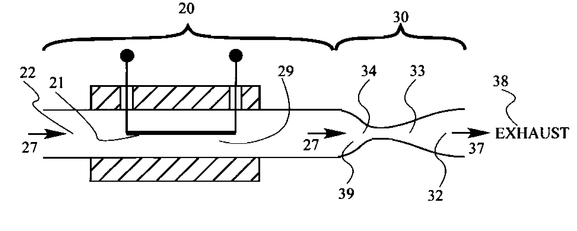
An apparatus and a method of making a measurement using the same. The apparatus includes a channel through which a fluid flows, a detector, and a choked flow channel. The detector measures a property of the fluid by generating a signal that depends on that property. The signal generated also depends on a pressure of the fluid in the detector. The choked flow channel receives the fluid at a first pressure after the fluid has been measured by the detector, and then transmits the fluid to a downstream location at a second pressure. The fluid reaches a supersonic velocity at one point in the choked flow channel. The choked flow channel may include a convergent-divergent nozzle or an orifice in a structure located in the choked flow channel.

Description

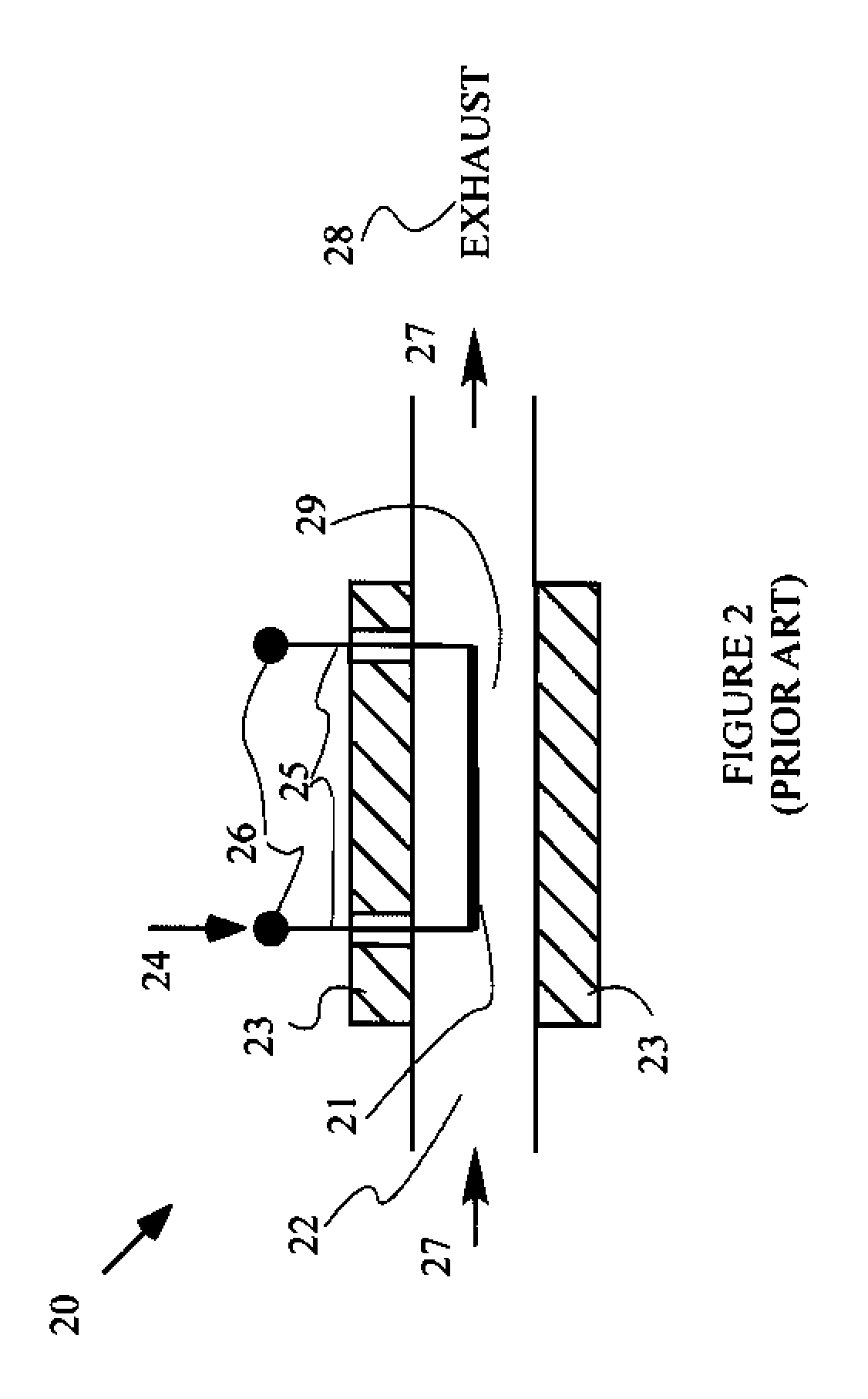
BACKGROUND OF THE INVENTION[0001]Gas chromatographs are used to separate mixtures of gaseous compounds into the individual components and then measure the concentration of each component. The sample to be analyzed is injected into a separation column in a carrier gas that flows through the column. The time needed for a particular chemical component to traverse the column depends on the interactions between the component and the column material. Hence, the components are separated in space as the components move through the column and exit the column at different times. The amount of material leaving the column is measured by some form of detector to provide an analysis of the original sample. The gas then exits the system.[0002]Gas chromatographs often utilize detectors that measure the thermal conductivity of the gas leaving the column. The detectors respond to the changes in thermal conductivity of the gas, and hence, are sensitive to the pressure of the gas at the detector, becau...

Claims


Application Information

Patent Timeline
Patent Type & Authority Applications(United States)
IPC IPC(8): G01N30/04
CPCG01N2030/324G01N30/32
Inventor BARTH, PHILLIP W.
Owner AGILENT TECH INC
Learn More