Rudder roll stabilization by nonlinear dynamic compensation

a nonlinear dynamic compensation and roll stabilization technology, applied in the direction of special-purpose vessels, vessel movement reduction by foils, instruments, etc., can solve the problems of reduced crew effectiveness, cargo damage, and movement on the roll axis of a ship that can have several detrimental effects, so as to prevent unstable filter conditions, maintain stability, and reduce the performance of steering mechanisms

Inactive Publication Date: 2010-06-17
UNIVERSITY OF WYOMING
View PDF2 Cites 9 Cited by
  • Summary
  • Abstract
  • Description
  • Claims
  • Application Information

AI Technical Summary

Benefits of technology

[0009]To achieve the foregoing and other objects, and in accordance with the purposes of the present invention, as embodied and broadly described herein, the method for rudder roll stabilization using multipath-feedback nonlinear dynamic compensation hereof includes the steps of: comparing the inverted ship's roll sensor output to the output of a nonlinear dynamic compensator; inputting the resulting signal to the roll compensator, Cr(s); comparing the chosen heading to the ship's heading sensor output, defining thereby the heading error; inputting the heading error into the heading compensator, Cy(s); adding the heading compensator and roll compensator outputs; inputting this result into the steering mechanism, thereby defining the rudder angle command; simultaneously inputting the rudder command input to the nonlinear dynamic compensator; whereby in the unsaturated condition, the outputs of summing junctions of the nonlinear dynamic compensator are zero, and the output of the nonlinear dynamic compensator is zero, and if the rudder is rate saturated, a rate-loop saturation element in th...

Problems solved by technology

Motion on a ship's roll axis can have several detrimental effects including cargo damage, reductions in crew effectiveness and increased pilot workload in helicopter landings.
Drawbacks of RRS have included the lack of performance at low speed, the need for a high speed rudder mechanism and the feedback limitations of the roll control loop.
Thus, the yaw and roll loops are designed with sufficient bandwidth separation, whi...

Method used


Image

  • Rudder roll stabilization by nonlinear dynamic compensation
  • Rudder roll stabilization by nonlinear dynamic compensation
  • Rudder roll stabilization by nonlinear dynamic compensation

Examples


example

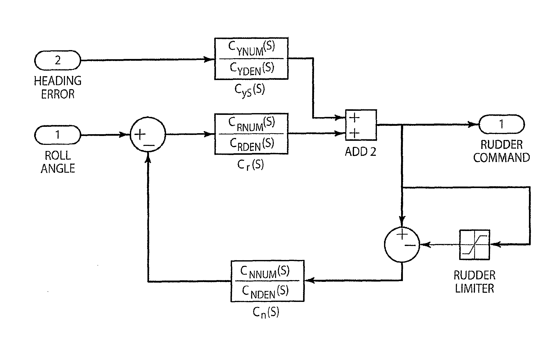
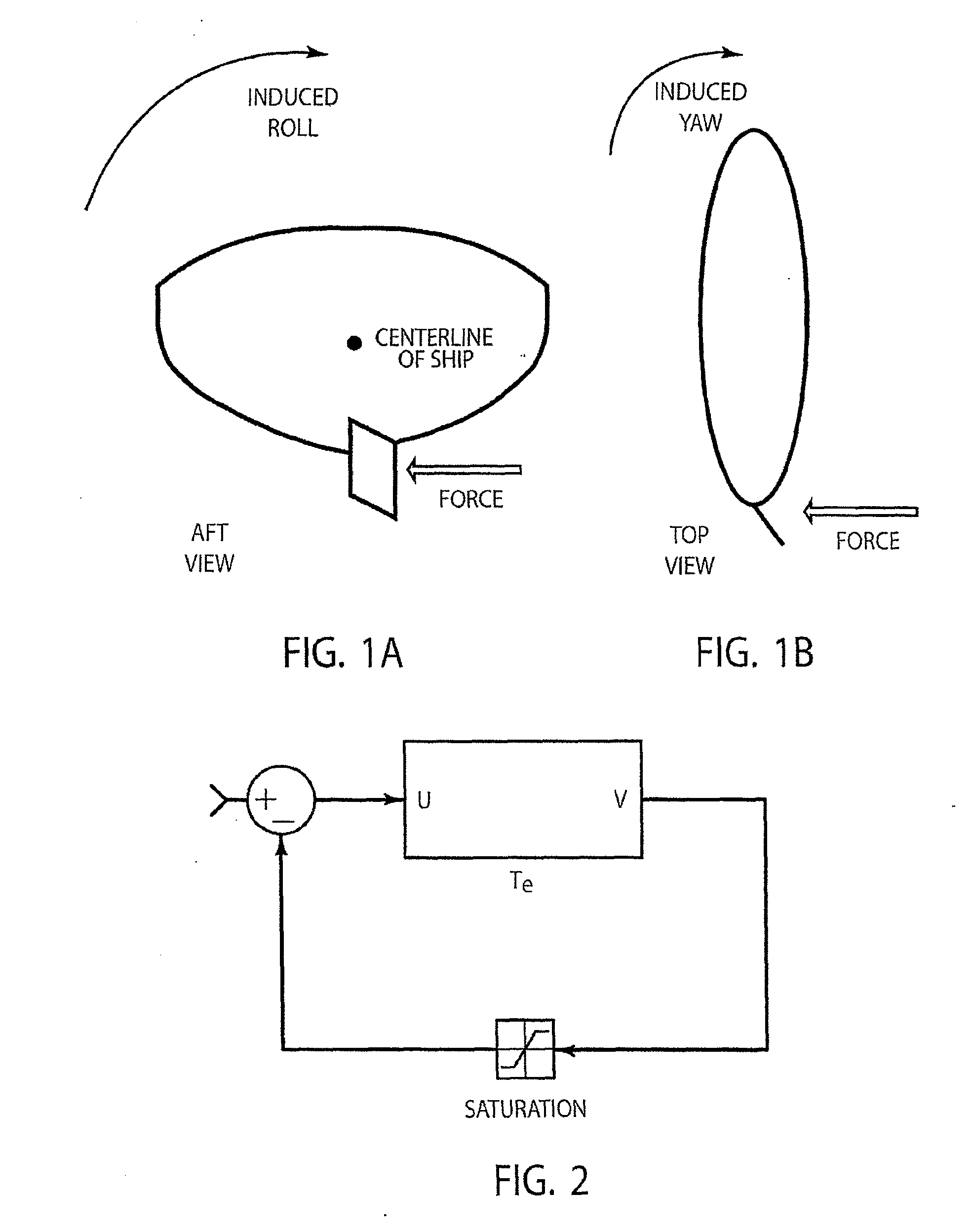
[0035]An embodiment of rudder roll stabilizer, 10, of the present invention is shown in FIG. 6 hereof. The blocks outside steering mechanism controller group, 12, are components of the heading controller / roll stabilizer. Steering mechanism 12 illustrates a simplified mathematical model of a rudder control loop. Rudder angle, 13, is limited in angle by limiter, 14, and the hydraulic steering machine is limited in rate by limiter, 16, the effects of which are modeled as saturations (rudder limiter and rudder rate limiter, respectively). These saturations limit performance and potentially threaten the stability of the feedback system. In the analysis set forth hereinabove, the angle limit was chosen to be 35° / s, and as stated, three rate limits were considered (10° / s, 15° / s, and 20° / s). The limiters are specifically designed using identified vessel dynamics and rudder characteristics. The following describes the function of the multi-feedback-path nonlinear dynamic compensator shown in...


PUM


Abstract

A method for rudder roll stabilization having two-feedback-path nonlinear dynamic compensation (NDC) is described. The high-order, Nyquist-stable control system having NDC hereof is absolutely stable and will provide a 20%-40% improvement in performance over existing roll reduction designs when lower performance steering mechanisms are employed, and is superior to linear controllers. That is, the present invention will be effective rudder roll stabilization in commercial vessels having slower rudders as well as in vessels having steering machines representing the best performance currently available, such as military systems. Since no ship hardware modifications are required, the present roll control technology will be able to be economically implemented.

Description

RELATED CASES[0001]The present application claims the benefit of provisional patent application Ser. No. 61 / 121,700 for “Rudder Roll Stabilization By Nonlinear Dynamic Compensation” by John F. O'Brien, filed on 11 Dec. 2008, which provisional application is hereby incorporated by reference herein for all that it discloses and teaches.FIELD OF THE INVENTION[0002]The present invention relates generally to roll stabilization of ships using a rudder for controlling heading while simultaneously reducing rolling motion and, more particularly, to the use of the vessel's rudder and a high-order, Nyquist-stable control system having two nonlinear dynamic compensation feedback paths for providing roll reduction without experiencing instability for such systems in the presence of either rudder angle or rudder movement rate saturation.BACKGROUND OF THE INVENTION[0003]Motion on a ship's roll axis can have several detrimental effects including cargo damage, reductions in crew effectiveness and in...

Claims


Application Information

Patent Timeline
IPC IPC(8): B63B43/04B63H25/06
CPCB63B39/06B63H25/18B63H25/06
Inventor O'BRIEN, JOHN F.
Owner UNIVERSITY OF WYOMING
Why Eureka
Try Eureka