Thermal energy storage apparatus

Inactive Publication Date: 2010-06-17
VETROVEC JAN
View PDF9 Cites 13 Cited by
  • Summary
  • Abstract
  • Description
  • Claims
  • Application Information

AI Technical Summary

Benefits of technology

[0009]The present invention provides a TES apparatus having a fast response to

Problems solved by technology

The absorption of the necessary quantity of energy by the solid PCM results in melting.
Many PCM capable of storing significant amount of heat are also very poor thermal conductors.
This makes it very challenging to transport heat into and out of the PCM, and limits the usefulness of such PCM

Method used


Image

  • Thermal energy storage apparatus
  • Thermal energy storage apparatus
  • Thermal energy storage apparatus

Examples


Embodiment Construction

[0019]Selected embodiments of the present invention will now be explained with reference to drawings. In the drawings, identical components are provided with identical reference symbols. It will be apparent to those skilled in the art from this disclosure that the following descriptions of the embodiments of the present invention are merely exemplary in nature and are in no way intended to limit the invention, its application, or uses.

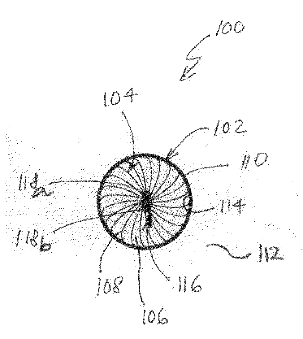
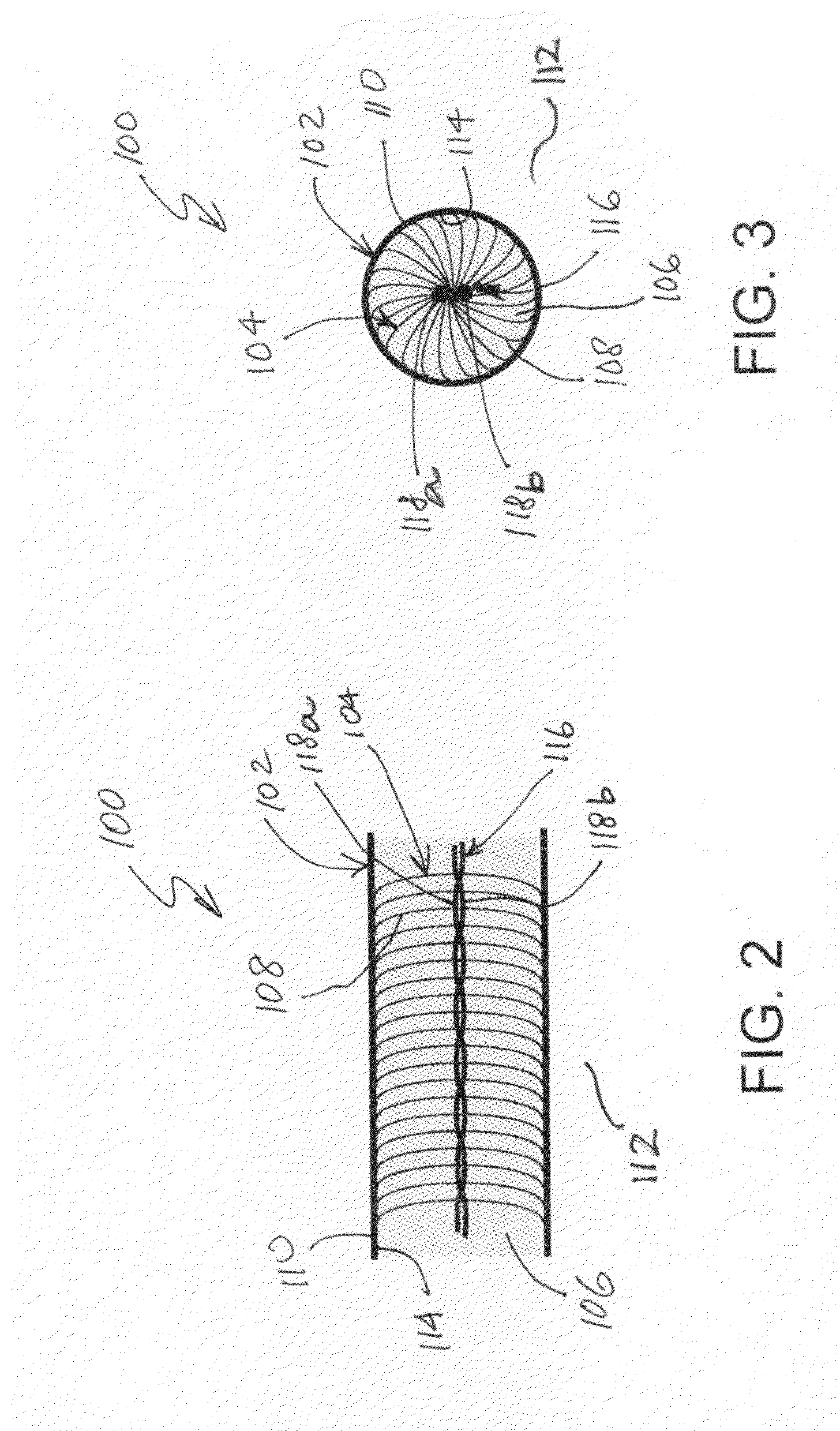
[0020]Referring now to FIG. 2, there is shown a cross-sectional view through the TES apparatus 100. The TES apparatus 100 comprises a tubular container 102, heat spreading element (HSE) 104, and PCM 106. The tubular container 102 is preferably made of material having good thermal conductivity, such as, but not limited to copper, copper alloys, aluminum, and aluminum alloys. The tubular container 102 has an external surface 110 adapted for communicating heat to and from a medium 112, such as gas, air, liquid, solid, or an environment. In some variants o...


PUM


Abstract

The present invention provides a thermal energy storage (TES) apparatus having a fast response to heat, which is also simple, lightweight, compact, and inexpensive to fabricate. In one preferred embodiment of the present invention, phase change material (PCM) is enclosed in a tubular container. A brush-like heat spreading element having radial bristles is installed in the tube within the PCM. The bristles are made of wires or fibers having good thermal conductivity and their ends are in a good thermal contact with the interior wall of the tube. Heat from external source is deposited into the tube exterior and conducted through the wall, transferred to the bristles, and conducted through the bristles in a generally radial direction substantially through out the PCM volume. The TES may be used in buildings to stabilize temperature and thus reduce the cost of building climate control such as heating and air conditioning.

Description

CROSS-REFERENCE TO RELATED APPLICATIONS[0001]This application claims priority from the U.S. provisional patent application U.S. Ser. No. 61 / 201,885, filed on Dec. 16, 2008, entitled “THERMAL ENERGY STORAGE APPARATUS.”GOVERNMENT RIGHTS IN THIS INVENTION[0002]This invention was made with U.S. government support under contract number FA8650-08-M-5026. The U.S. government may have certain rights in this invention.FIELD OF THE INVENTION[0003]This invention relates generally to apparatus and methods for conduction of heat and more specifically to to apparatus and methods for storage of thermal energy.BACKGROUND OF THE INVENTION[0004]The invention is for a thermal energy storage (TES) apparatus and method. TES is often used in devices and systems to temporarily store heat. For example, a TES apparatus may be used to average out a temperature in a heating system in a building or a vehicle with the objective of reducing the cost of energy expended in heating. In particular, TES can reduce th...

Claims


Application Information

Patent Timeline
IPC IPC(8): F28D17/00F28D15/00
CPCY02E60/145F28D20/02Y02E60/14
Inventor VETROVEC, JAN
Owner VETROVEC JAN
Why Eureka
Try Eureka