Light-emitting keyboard
a keyboard and light-emitting technology, applied in the field of light-emitting keyboards, can solve the problems of increasing the complexity of the manufacturing process, increasing the manufacturing cost, and increasing the difficulty of assembly, and achieve the effect of reducing the thickness
- Summary
- Abstract
- Description
- Claims
- Application Information
AI Technical Summary
Benefits of technology
Problems solved by technology
Method used
Image

Examples
first embodiment
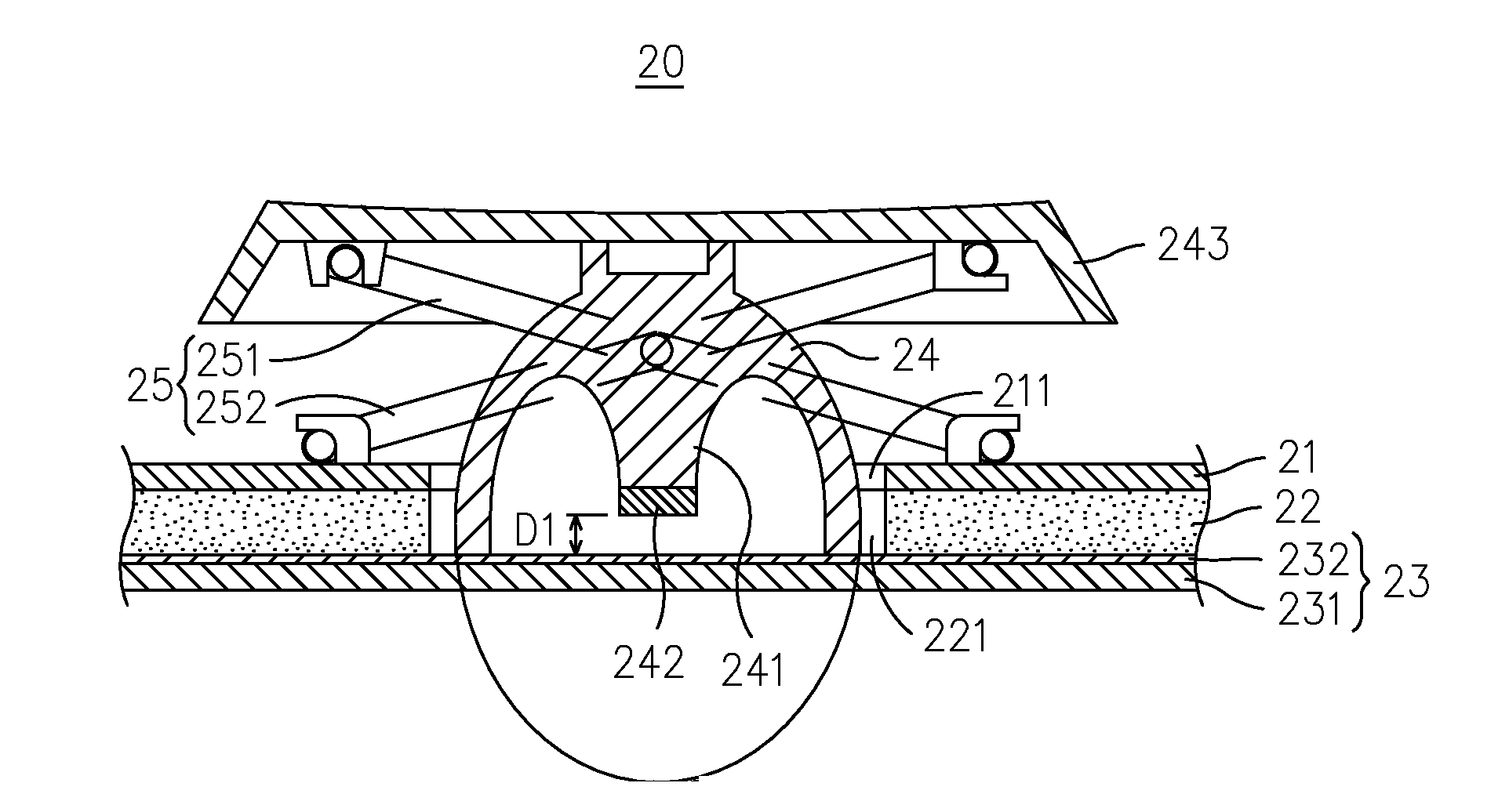
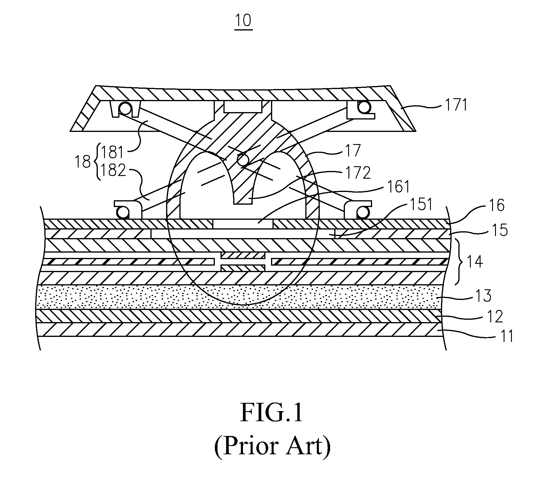
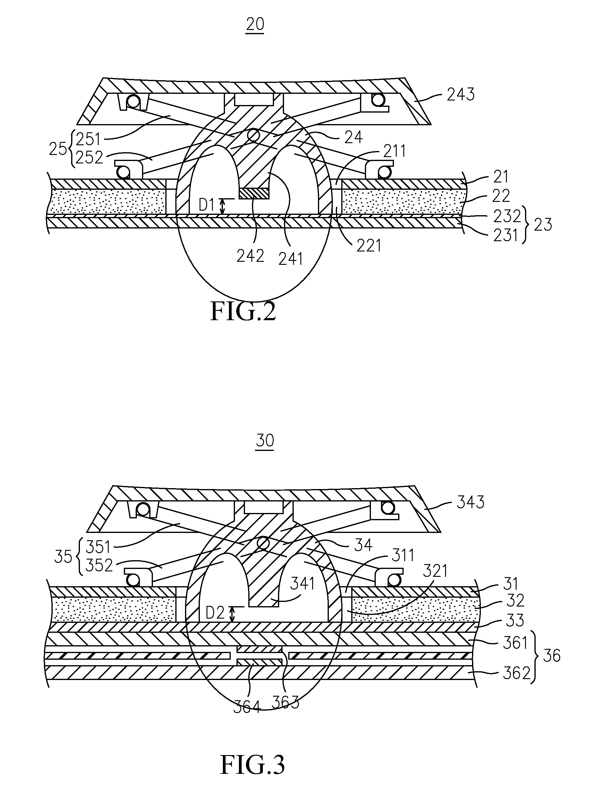
[0015]Please refer to FIG. 2, which is a schematic diagram showing a press key in a light-emitting keyboard according to the invention. In FIG. 1, the press key 20 comprises: a support panel 21, configured with a first hole 211; a light guide plate 22, being disposed at the bottom of the support panel 21 and configured with a second hole 221 at a position thereof corresponding to the first hole 211; a reflection plate circuit assembly 23, disposed at the bottom of the light guide plate 22 and composed of a reflection plate 231 and a circuit 232 in a manner that the circuit 232 is formed on top of the reflection plate 231; and an elastic member 24, being disposed inside the corresponding first hole 211 and second hole 221 while enabling the bottom thereof to abut against the reflection plate circuit assembly 23. Moreover, the elastic member 24 is configured with an activating post 241 at the center thereof whereas the activating post 241 is further configured with an electric conduct...
second embodiment
[0023]Please refer to FIG. 3, which is a schematic diagram showing a press key in a light-emitting keyboard according to the invention. In FIG. 3, the press key 30 is a stacking structure composed of a support panel 31, a light guide plate 32, a reflection plate 33 form top to bottom, in which the support panel 31 is formed with a first hole 311 and the light guide plate 32 is formed with a second hole 321 whereas there is an elastic member 34 having an activating post 341 being received inside the first hole 311 and the second hole 321. When the elastic member 34 is not being pressed, as the status shown in FIG. 3, the bottom of the activating post 341 will be separated from the reflection plate 33 by a specific distance D2. In addition, there is a keycap 343 mounted on top of the elastic member 34 while there is a scissors-type structure 35 sandwiched between the keycap 343 and the support panel 31, and the scissor-type structure 35, being composed of a first supporting arm 351 an...
third embodiment
[0024]Please refer to FIG. 4, which is a schematic diagram showing a press key in a light-emitting keyboard according to the invention. In FIG. 4, the press key 40 includes a support panel 41, a light guide plate 42, a reflection plate 43, an elastic member 44, an activating post 441, a keycap 443, a scissor-type structure 45, which is similar to those shown in FIG. 2 and FIG. 3. The press key 40 of the present embodiment is characterized in that: there is a circuit board 43 disposed at the bottom of the reflection plate 43, which is composed of a substrate 461 and a circuit, whereas the circuit 462 is disposed on a top surface of the substrate 461. It is noted that the substrate 461 can be made of a flexible material or a rigid material. As there is a third hole 431 formed on the reflection plate 43 at a position corresponding to the activating post 441, and there is an electric conductor 442 arranged at the bottom of the activating post 441, an electric conduction will be construc...
PUM
 Abstract
Description
Claims
Application Information
 - R&D
- Intellectual Property
- Life Sciences
- Materials
- Tech Scout
- Unparalleled Data Quality
- Higher Quality Content
- 60% Fewer Hallucinations
Browse by: Latest US Patents, China's latest patents, Technical Efficacy Thesaurus, Application Domain, Technology Topic, Popular Technical Reports.
© 2025 PatSnap. All rights reserved.Legal|Privacy policy|Modern Slavery Act Transparency Statement|Sitemap|About US| Contact US: help@patsnap.com