Wind turbine generating apparatus

a technology of wind turbines and generating equipment, which is applied in the direction of mechanical equipment, electric generator control, machines/engines, etc., can solve the problems of increasing the internal temperature caused by the increase in the heat generation amount of internal devices, the situation becomes severe for the control devices configured by electric/electronic parts, and the size of the wind turbine blades. to achieve the effect of improving the reliability and durability of the wind turbine power generating apparatus, increasing the heat transfer amount, and improving the reliability

Inactive Publication Date: 2010-06-17
MITSUBISHI HEAVY IND LTD
View PDF10 Cites 21 Cited by
  • Summary
  • Abstract
  • Description
  • Claims
  • Application Information

AI Technical Summary

Benefits of technology

[0025]According to the third mode of the present invention, the heat dissipating means is provided to at least one of the rotor head and the hub, so that the heat transfer amount between the outsides and insides of the rotor head and the hub can be increased without deteriorating air-tightness. As the heat dissipating means in this case, a cooling heat transfer element such as a Peltier element, a radiation fin, or the like is effectively employed.
[0026]According to the present invention, by introducing air of a relatively low temperature from the inside of the nacelle or introducing outside air directly to the inside of the rotor head and circulating the

Problems solved by technology

In the above wind turbine generating apparatus, as an output increases in recent years, there is a tendency that the wind turbine blades are also becoming larger.
Since such increase in the heat generation amount raises the internal temperature of the hub 4, the situation becomes severe for the control devices configured by elec

Method used


Image

  • Wind turbine generating apparatus
  • Wind turbine generating apparatus
  • Wind turbine generating apparatus

Examples


first embodiment

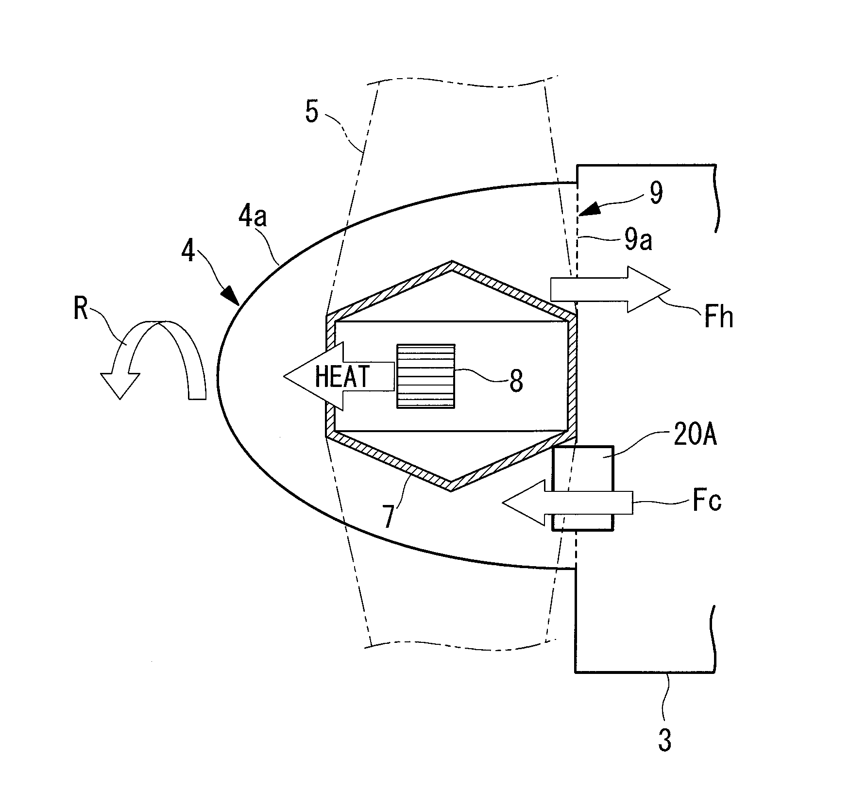
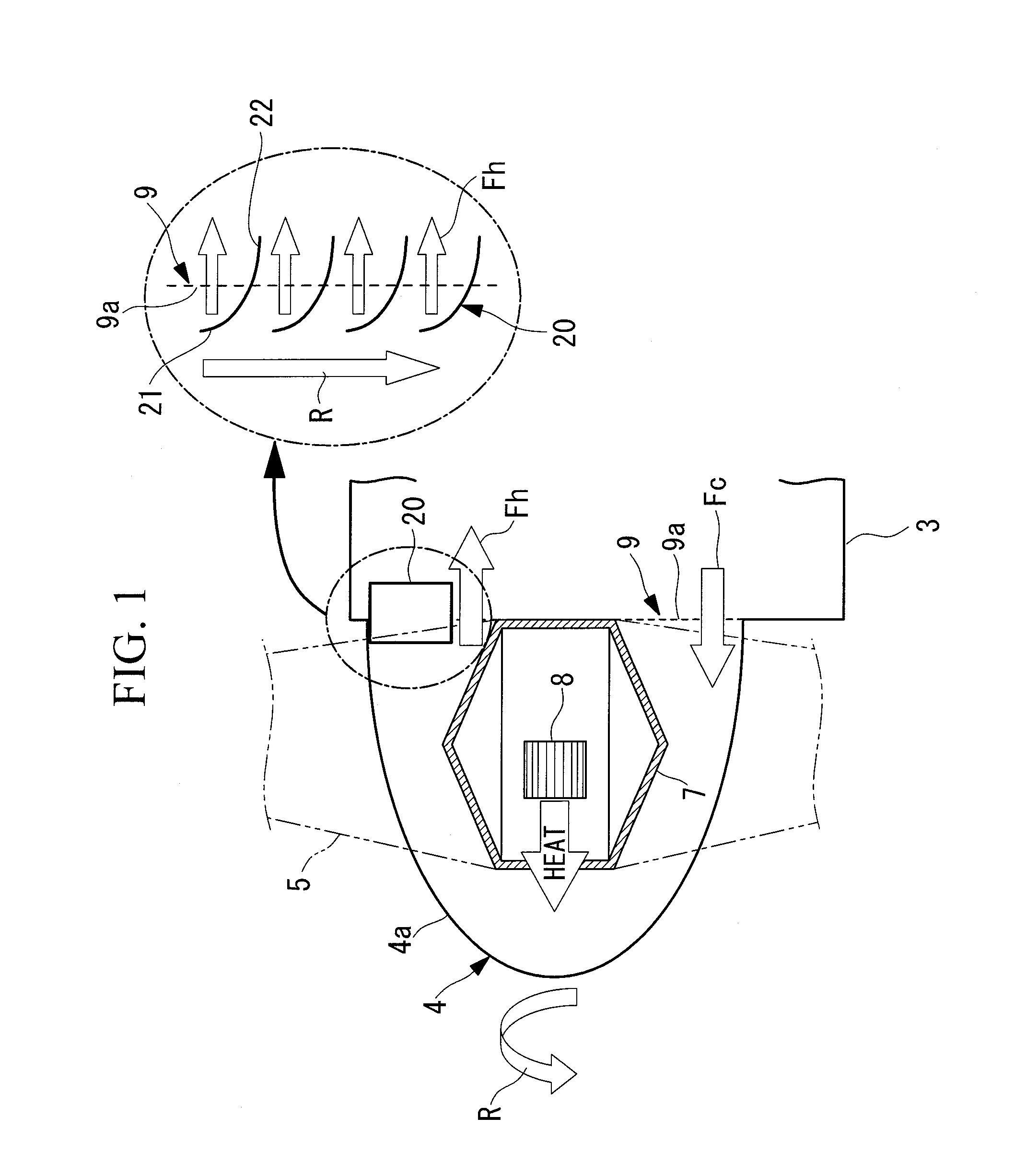
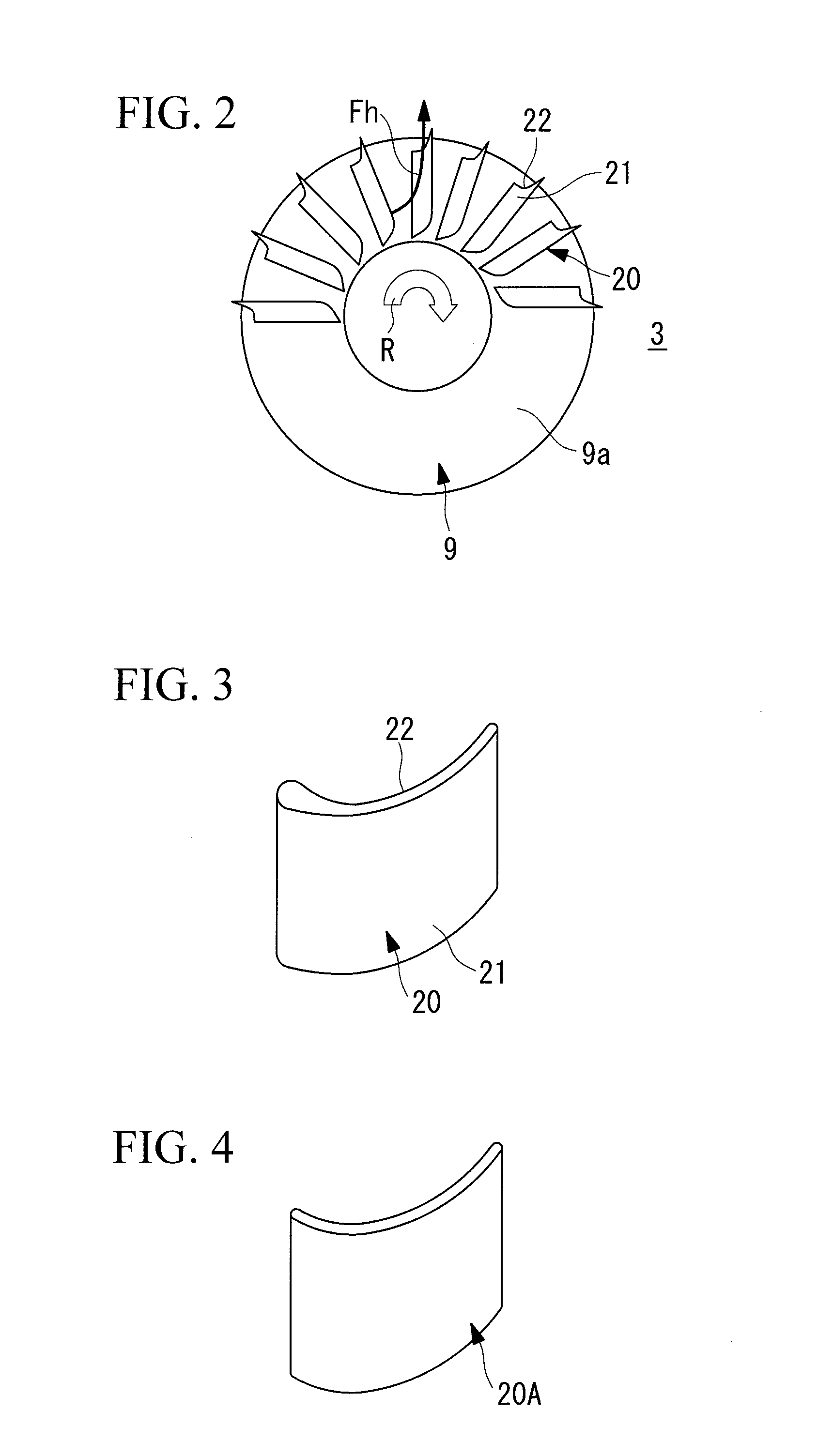
[0084]In a first embodiment shown in FIGS. 1 to 3, the air flow forming means for forming an air flow corresponds to an air circulation guide (hereinbelow, called “guide”) 20 mounted in the communication path 9. The guide 20 is, for example, a blade-shaped member as shown in FIG. 3, and a plurality of guides 20 are disposed at equal pitches over an almost semiperimeter in the circumferential direction of the communication path 9 having a circular shape. In the configuration example shown in the drawings, the guides 20 are attached over the upper half of the semiperimeter (hereinbelow, called “upper region”) of the communication path 9. However, the present invention is not limited to such a configuration. In the blade shape of the guide 20 shown in FIG. 3, reference 21 in the drawing denotes the back thereof, and 22 denotes the front thereof.

[0085]In the configuration shown in FIGS. 1 and 2, the plurality of guides 20 are attached to the nacelle 3 on the stationary side. That is, th...

second embodiment

[0094]Subsequently, a second embodiment of the present invention will be described with reference to FIGS. 7 and 8. The same references are designated to parts similar to those of the foregoing embodiment and detailed description thereof will not be given.

[0095]In this embodiment, a partition member 9b such as a punching metal for partitioning the communication path 9 is attached to the rotor head 4 side. An air circulation guide (hereinbelow, called “rotation guide”) 20A is attached to the communication path 9 as air flow forming means for forming an air flow. As the rotation guide 20A, for example, a blade-shaped member shown in FIG. 3 or a blade-shaped curved plate shown in FIG. 4 is employed. A plurality of rotation guides 20A are disposed at equal pitches over almost a semiperimeter in the circumferential direction of the circular-shaped communication path 9. In the blade shape of the rotation guide 20 illustrated in FIG. 3, reference 21 in the diagram denotes the back thereof,...

third embodiment

[0103]Subsequently, a third embodiment of the present invention will be described with reference to FIGS. 9 and 10. The same references are designated to parts similar to those of the foregoing embodiments and detailed description thereof will not be given.

[0104]In this embodiment, partition members 9a and 9b such as punching metals each for partitioning the communication port 9 are attached to both of the nacelle 3 and the rotor head 4 so as to partition the space, for example, in the radial direction. In the example shown in the drawing, the partition members 9a are attached in almost a half of the outer periphery on the nacelle 3 side of the communication path 9, and the partition members 9b are attached in almost a half of the inner periphery of the rotor head 4.

[0105]The air flow forming means in this case employs a combination of the guides 20 described in the first embodiment and the rotation guides 20A described in the second embodiment. Specifically, the guides 20 fixed to ...


PUM


Abstract

The invention provides a wind turbine generating apparatus capable of controlling a temperature in a rotor head. In a wind turbine generating apparatus in which a driving/generating mechanism coupled to a rotor head having wind turbine blades attached thereto is housed in a nacelle, and control devices are housed in a hub of the rotor head, an air circulation guide is provided for allowing air to circulate between an inside of the rotor head and an inside of the nacelle via a communication path formed between the rotor head and the nacelle.

Description

CROSS-REFERENCE TO RELATED APPLICATIONS[0001]The present application is based on International Application No. PCT / JP2008 / 068025, filed on Oct. 3, 2008, which in turn corresponds to Japanese Application No. 2007-261721 filed on Oct. 5, 2007, and priority is hereby claimed under 35 USC §119 based on these applications. Each of these applications are hereby incorporated by reference in their entirety into the present application.TECHNICAL FIELD[0002]The present invention relates to a wind turbine generating apparatus for generating power by using a wind turbine that converts wind as natural energy to a rotational force.BACKGROUND ART[0003]Conventionally, there is known a wind turbine generating apparatus for generating power by using a force of wind as natural energy. In a wind turbine generating apparatus of this kind, a nacelle mounted on a support is provided with a rotor head to which wind turbine blades are attached, a main shaft coupled so as to rotate integrally with the rotor ...

Claims


Application Information

Patent Timeline
IPC IPC(8): F03D9/00
CPCF03D11/00F05B2240/12F05B2240/14F05B2260/20Y02E10/726F05B2260/64F05B2260/74Y02E10/721Y02E10/722F05B2260/205F03D80/60Y02E10/72F03D1/00
Inventor SATO, SHINSUKESATO, TOSHIHIROFUKUDA, HIDEOKUSHIOKA, KIYONORIHIRAI, SHIGETOSAKATA, NOBUYASUSHIRAISHI, TATSUYA
Owner MITSUBISHI HEAVY IND LTD
Why Eureka
Try Eureka