Methods and apparatus for particle detection

a particle detection and particle technology, applied in the field of methods and apparatus for particle detection, can solve the problems of complex substrate structure, increased detector cost, and inability to be easily re-used

Inactive Publication Date: 2010-06-17
BYOTROL PLC
View PDF10 Cites 10 Cited by
  • Summary
  • Abstract
  • Description
  • Claims
  • Application Information

AI Technical Summary

Problems solved by technology

A problem with the aforementioned methods is that a complex substrate structure, which includes structured layers of different materials, is required to be built up to make the sensor.
Typically, the sensor is made for a single use only, since it is made specifically for the detection of a particular type or selection of molecules to be detected, and cannot readily be re-used.
This increases the cost of the detector.

Method used


Image

  • Methods and apparatus for particle detection
  • Methods and apparatus for particle detection
  • Methods and apparatus for particle detection

Examples


Embodiment Construction

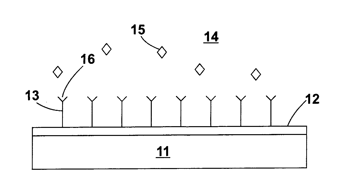
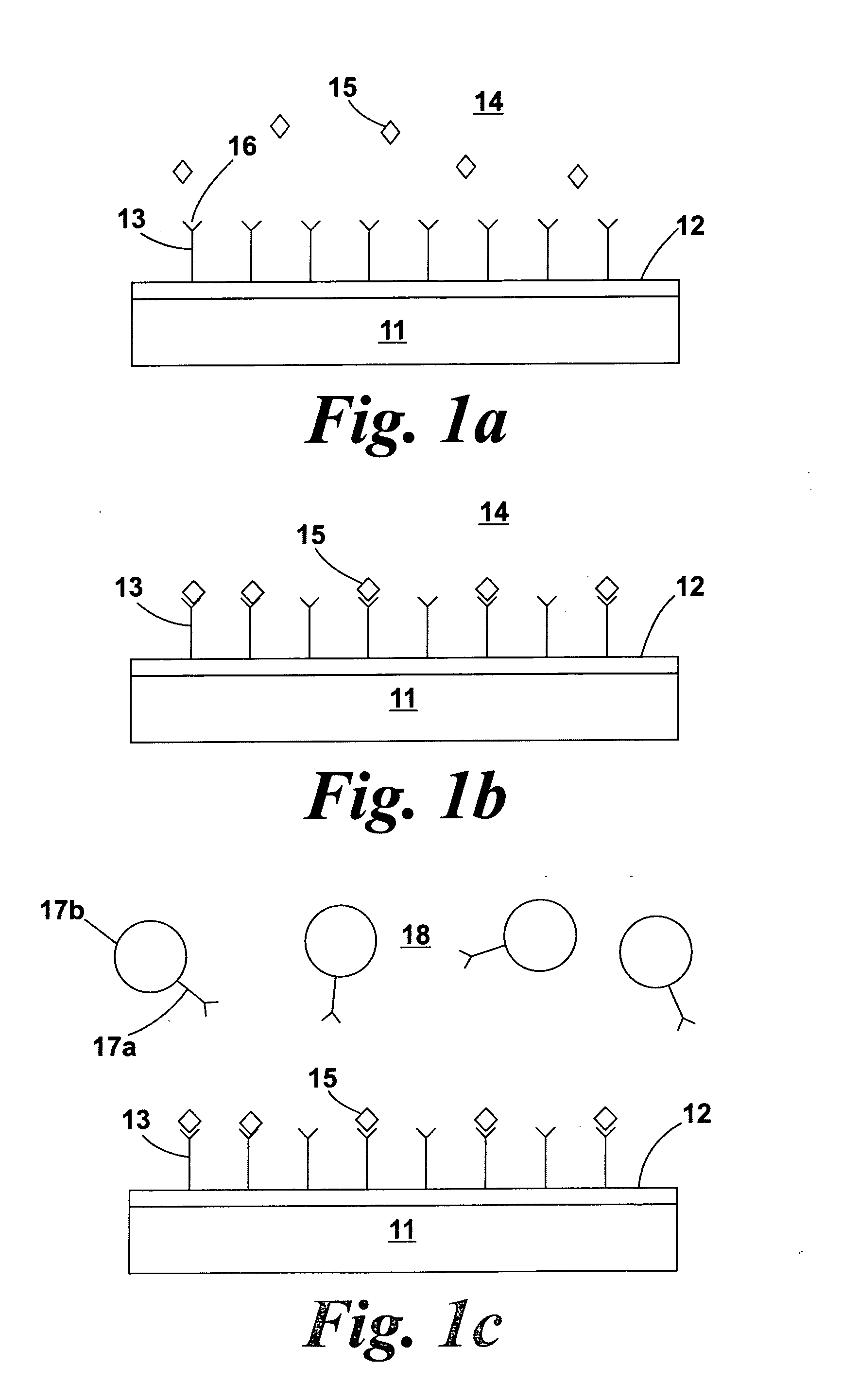
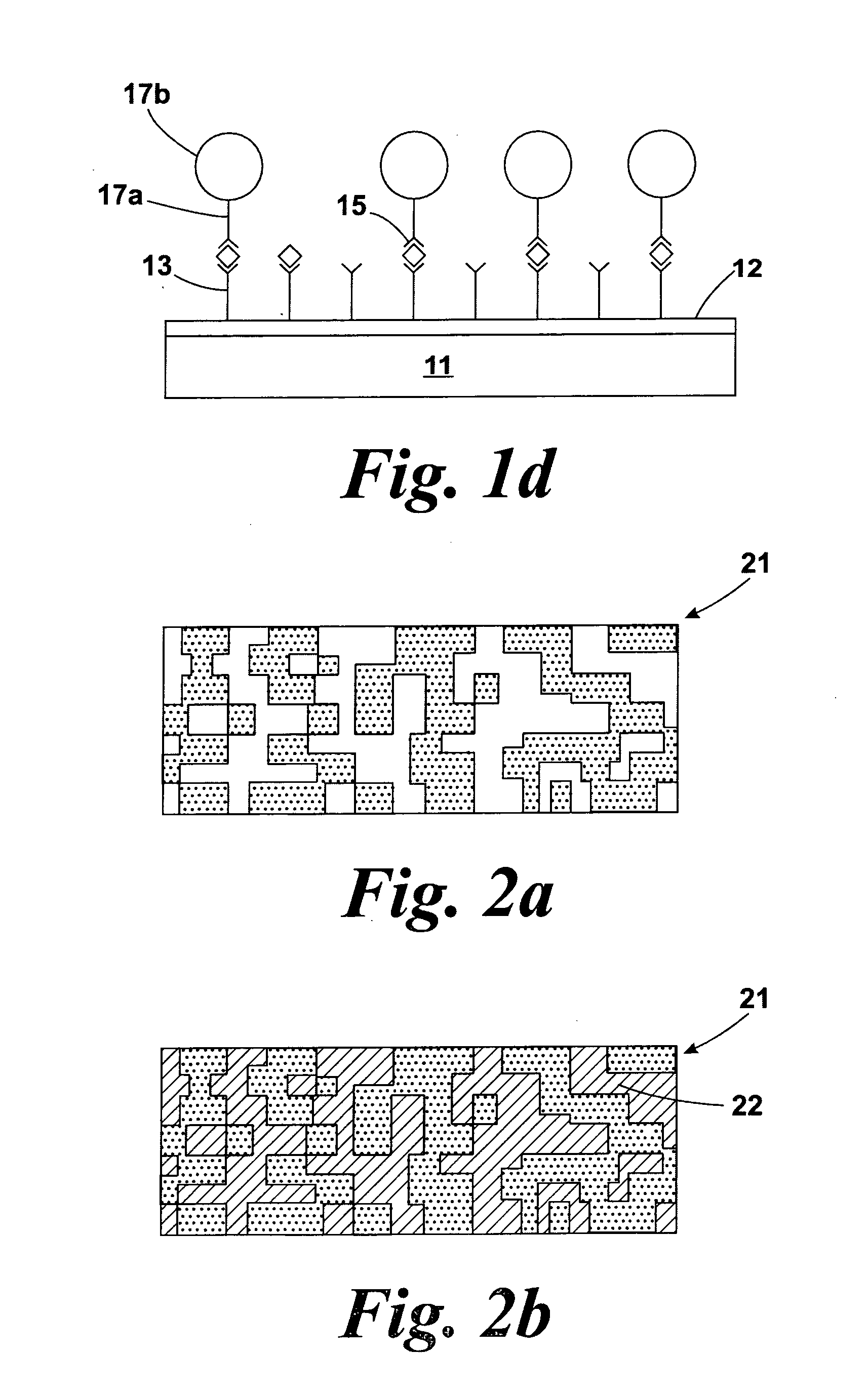
[0037]FIGS. 1a to 1d have already been described as part of the background to the invention.

[0038]FIGS. 2a to 2e illustrate various steps of a method of preparing a substrate for detection of a compound.

[0039]It should be noted that certain embodiments of the present invention are performed directly on the substrates 21 which originally comprise the substance 32 to be detected (e.g. directly on a table surface in a hospital i.e. in situ), but other embodiments are formed on test strips / substrates 21 to which the substance 32 to be detected has been transferred (e.g. taking a sample / swab from the table surface in a hospital and performing the test on the sample / swab) i.e. indirect testing.

[0040]A test strip or substrate may be a porous or otherwise bibulous member, for example a nitrocellulose strip. An exemplary porous substrate 21 is illustrated schematically in cross-section in FIG. 2a. The pore size of the substrate is preferably less than 500 nm.

[0041]The invention is not, howev...


PUM


Abstract

A method of detecting the presence of a substance (32) to be detected on a surface of a substrate (21), the method comprising: i) providing magnetic particles (35) to the substrate (21) for binding with the substance (32) to be detected; and ii) determining the presence of the substance (32) to be detected by detecting the magnetoresistive effect of the magnetic particles (35) bound to the substance (32) to be detected on a magnetoresistive element (40) positioned proximate the substrate surface.

Description

FIELD OF THE INVENTION[0001]The invention relates to methods and apparatus for the detection of a substance to be detected on a substrate by using magnetic particles. Particular embodiments of the invention are suited for use in detecting biological / chemical substances which may be harmful to health.BACKGROUND TO THE INVENTION[0002]Various methods and apparatus for detection of substances using magnetic beads bound to biologically active compounds such as antibodies are known. US 2004 / 0033627, for example, discloses a method using magnetic beads and electrical circuits to detect chemicals, including an addressable array of detectors on to which detector molecules such as antibodies, proteins, oligonucleotides or other binding molecules are bound. A liquid containing a substance of interest is added to the detector surface, and molecules of the substance to be detected bind to the detector molecules and thus to the substrate surface.[0003]FIG. 1a shows schematically the arrangement o...

Claims


Application Information

Patent Timeline
Patent Type & Authority Applications(United States)
IPC IPC(8): G01R33/12
CPCB82Y25/00G01N33/54333G01R33/1269G01R33/12G01R33/093G01N33/54326G01N35/0098G01R33/1215
Inventor SCHWARZ, ULRICH
Owner BYOTROL PLC
Why Eureka
Try Eureka