Systems and methods for an adaptive bias circuit for a differential power amplifier

a technology of differential power amplifiers and bias circuits, applied in the field of power amplifiers, can solve the problems of low efficiency and large linearity margins of amplifiers in low power regions, and achieve the effects of low efficiency, small linearity margins, and high efficiency

Inactive Publication Date: 2010-06-17
SAMSUNG ELECTRO MECHANICS CO LTD +1
View PDF16 Cites 18 Cited by
  • Summary
  • Abstract
  • Description
  • Claims
  • Application Information

AI Technical Summary

Benefits of technology

[0008]Example embodiments of the invention may provide for an adaptive bias circuit, which may include a differential amplifier, low-pass filter, and a common source amplifier if a field-effect transistor (FET) is utilized (or alternatively, a common emitter amplifier if a bipolar junction transistor (BJT) is utilized). In an example embodiment of the invention, the adaptive bias circuit may generate an adaptive bias output signal depending on an input signal power level. As input power level goes up, the adaptive bias circuit increases the bias voltage or bias current of the adaptive bias output signal. The adaptive bias output signal may be a gate bias voltage if received by a gate of a FET or otherwise a base current if received by a base of a BJT.
[0009]According to an example embodiment of the invention, there is an adaptive bias circuit for controlling an operations of an amplifier. The adaptive bias circuit may include a differential amplifier that receives differential input signals and generates amplified differential input signals; a current mirror that converts the amplified differential input signals into a single-ended signal; a low-pass filter that filters out one or more high-frequency components of the single-ended signal to generate a filtered single-ended signal; and a common-source amplifier or common-emitter amplifier that receives the filtered single-ended signal and generates an adaptive bias signal for operating a power amplifier.
[0010]According to another example embodiment of the invention, there is a power amplification system. The system may include a plurality of power amplifiers configured in parallel, where the plurality of power amplifiers receive at least one common input signal, where each of the plurality of power amplifiers generates a respective at least one amplified output signal, where respective at least one amplified output signal are combined to provide at least one combined amplified signal; and a plurality of adaptive bias circuits corresponding to each of the plurality of power amplifiers for providing a respective adaptive bias signal to the respective power amplifier, where at least two of the plurality of adaptive bias circuits have differing bias ranges for the provided respective adaptive bias signals. Each of at least two of the plurality of adaptive bias circuits may include a differential amplifier that receives differential input signals and generates amplified differential input signals; a current mirror that converts the amplified differential input signals to generate a single-ended signal; a low-pass filter that filters out one or more high-frequency components of the single-ended signal to generate a filtered single-ended signal; and a common-source amplifier or common-emitter amplifier that receives the filtered single-ended signal and generates the respective adaptive bias signal for operating the respective power amplifier.

Problems solved by technology

An amplifier typically has low efficiency and large linearity margins at low power regions, and high efficiency and small linearity margins at high power regions.

Method used


Image

  • Systems and methods for an adaptive bias circuit for a differential power amplifier
  • Systems and methods for an adaptive bias circuit for a differential power amplifier
  • Systems and methods for an adaptive bias circuit for a differential power amplifier

Examples


Embodiment Construction

[0020]Embodiments of the invention now will be described more fully hereinafter with reference to the accompanying drawings, in which some, but not all embodiments of the invention are shown. Indeed, these inventions may be embodied in many different forms and should not be construed as limited to the embodiments set forth herein; rather, these embodiments are provided so that this disclosure will satisfy applicable legal requirements. Like numbers refer to like elements throughout.

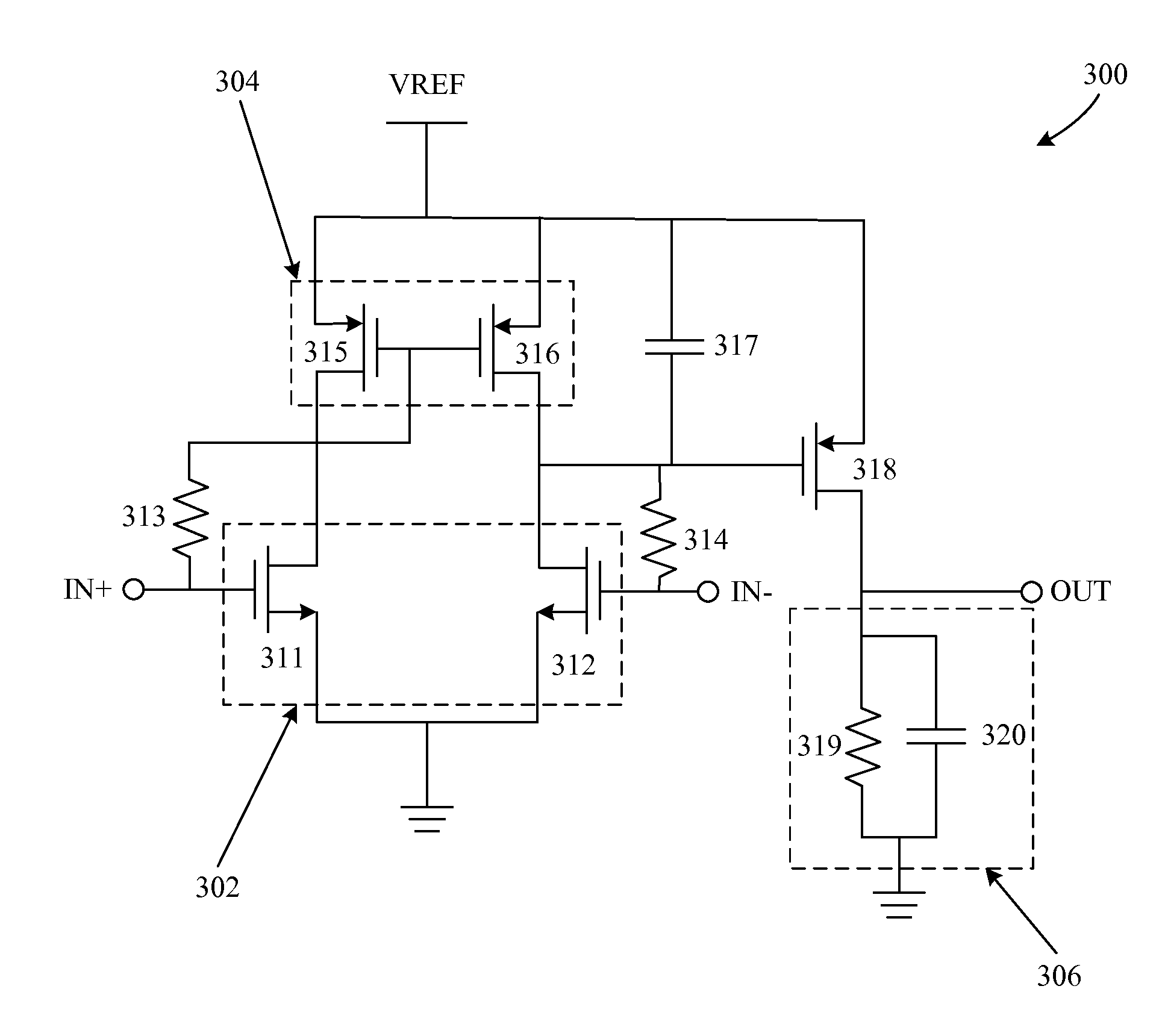
[0021]Embodiments of the invention may be directed to systems and methods for providing an adaptive bias circuit that may include one or more of a differential amplifier, a low-pass filter, and a common source amplifier if a field-effect transistor (FET) is utilized (or alternatively, a common emitter amplifier if a bipolar junction transistor (BJT) is utilized). The adaptive bias circuit may generate an adaptive bias output signal (e.g., a gate bias voltage if received by a gate of a FET or base current ...


PUM


Abstract

Systems and methods for providing an adaptive bias circuit that may include a differential amplifier, low-pass filter, and common source amplifier or common emitter amplifier. The adaptive bias circuit may generate an adaptive bias output signal depending on input signal power level. As the input power level goes up, the adaptive bias circuit may increase the bias voltage or bias current of the adaptive bias output signal. A power amplifier (e.g., a differential amplifier) may be biased according to the adaptive bias output signal in order to reduce current consumption at low power operation levels.

Description

RELATED APPLICATION[0001]This application claims priority to U.S. Provisional Application No. 61 / 121,798, filed on Dec. 11, 2008, and entitled “SYSTEMS AND METHODS FOR AN ADAPTIVE BIAS CIRCUIT FOR A DIFFERENTIAL POWER AMPLIFIER”, which is hereby incorporated by reference in its entirety as if fully set forth herein.FIELD OF INVENTION[0002]The invention relates generally to power amplifiers, and more particularly, to systems and methods for adaptive bias circuits for differential power amplifiers.BACKGROUND OF THE INVENTION[0003]An amplifier typically has low efficiency and large linearity margins at low power regions, and high efficiency and small linearity margins at high power regions. For linear amplifiers, the linearity is limited at the highest output power condition, which is known as the saturated region. The linearity and efficiency of an amplifier may be affected by the bias conditions of the amplifier. Adaptive biasing generates an appropriate bias to enhance the performan...

Claims


Application Information

Patent Timeline
Patent Type & Authority Applications(United States)
IPC IPC(8): H03F3/45
CPCH03F3/45179H03F2203/45541H03F2203/45394H03F1/30H03F3/20
Inventor LEE, DONG HOAN, KYU HWANHAN, JEONGHULEE, CHANG-HOLASKAR, JOY
Owner SAMSUNG ELECTRO MECHANICS CO LTD
Why Eureka
Try Eureka