Display Device, Liquid Crystal Monitor, Liquid Crystal Television Receiver, and Display Method

a technology of liquid crystal monitor and display method, which is applied in the field of display devices, can solve the problems of excessive brightness, inability to completely prevent the change of grayscale characteristics with the viewing angle, and excessive brightness of halftone luminance, so as to reduce discrepancy in each frame, reduce the spotty appearance of the user, and mitigate excess brightness phenomena

Inactive Publication Date: 2010-06-17
SHARP KK
View PDF15 Cites 31 Cited by
  • Summary
  • Abstract
  • Description
  • Claims
  • Application Information

AI Technical Summary

Benefits of technology

[0052]The present display method is a method used in the present display device. Therefore, these display methods better reduce discrepancy in each frame and mitigate excess brightness phenomena caused by the discrepancy than ordinary hold display methods. The methods reduce the spotty appearance felt by the user.
[0053]As described in the foregoing, the display device of the present invention (present display device) displays an image by dividing each frame into m subframes (m is an integer greater than or equal to 2) and includes a display section and a control section. The display section is provided by a liquid crystal display element and displays an image with luminance in accordance with a display signal voltage. The control section generates first to m-th display signals for the first to m-th subframes for output to the display section so that the dividing of the frames does not change a sum luminance output of the display section in each frame. The display section has pixels each containing a first subpixel and a second subpixel which are connected to the same source line and the same gate line. The control section creates a

Problems solved by technology

However, even VA panels, reputed to have a wide viewing angle, cannot completely prevent grayscale characteristics from changing with the viewing angle.
Th

Method used


Image

  • Display Device, Liquid Crystal Monitor, Liquid Crystal Television Receiver, and Display Method
  • Display Device, Liquid Crystal Monitor, Liquid Crystal Television Receiver, and Display Method
  • Display Device, Liquid Crystal Monitor, Liquid Crystal Television Receiver, and Display Method

Examples


embodiment 1

[0111]The following will describe an embodiment of the present invention.

[0112]A liquid crystal display of the present embodiment (present display device) has a liquid crystal panel of vertical alignment (VA) mode divided into a plurality of domains. The present display device functions as a liquid crystal monitor producing a display on a liquid crystal panel from externally supplied image signals.

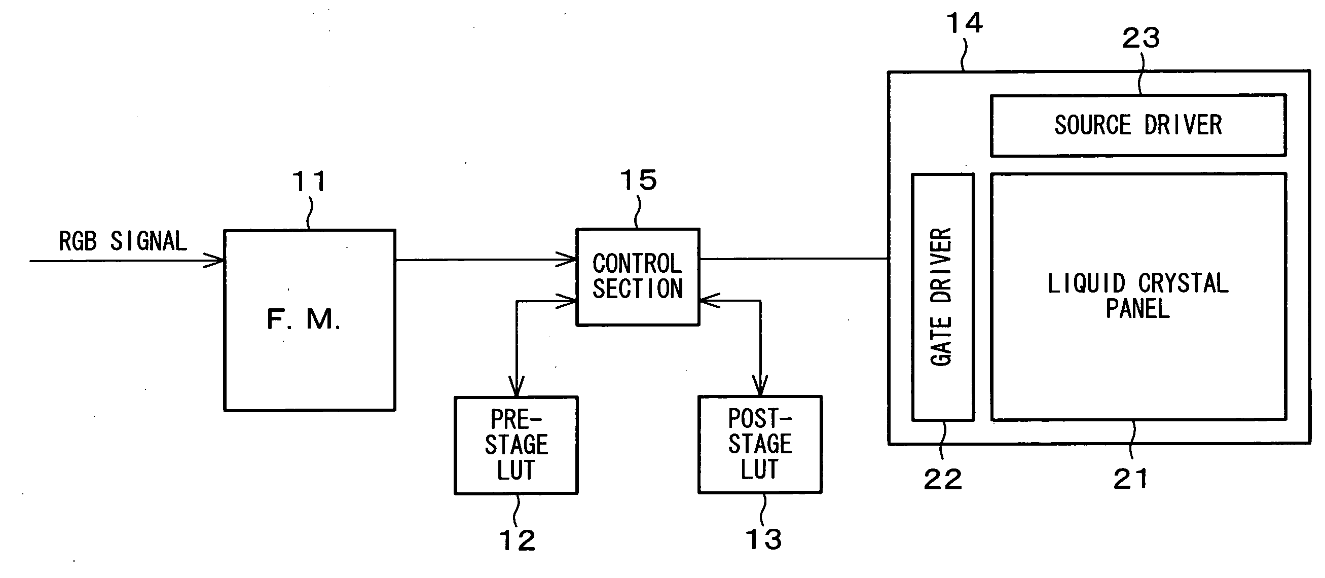
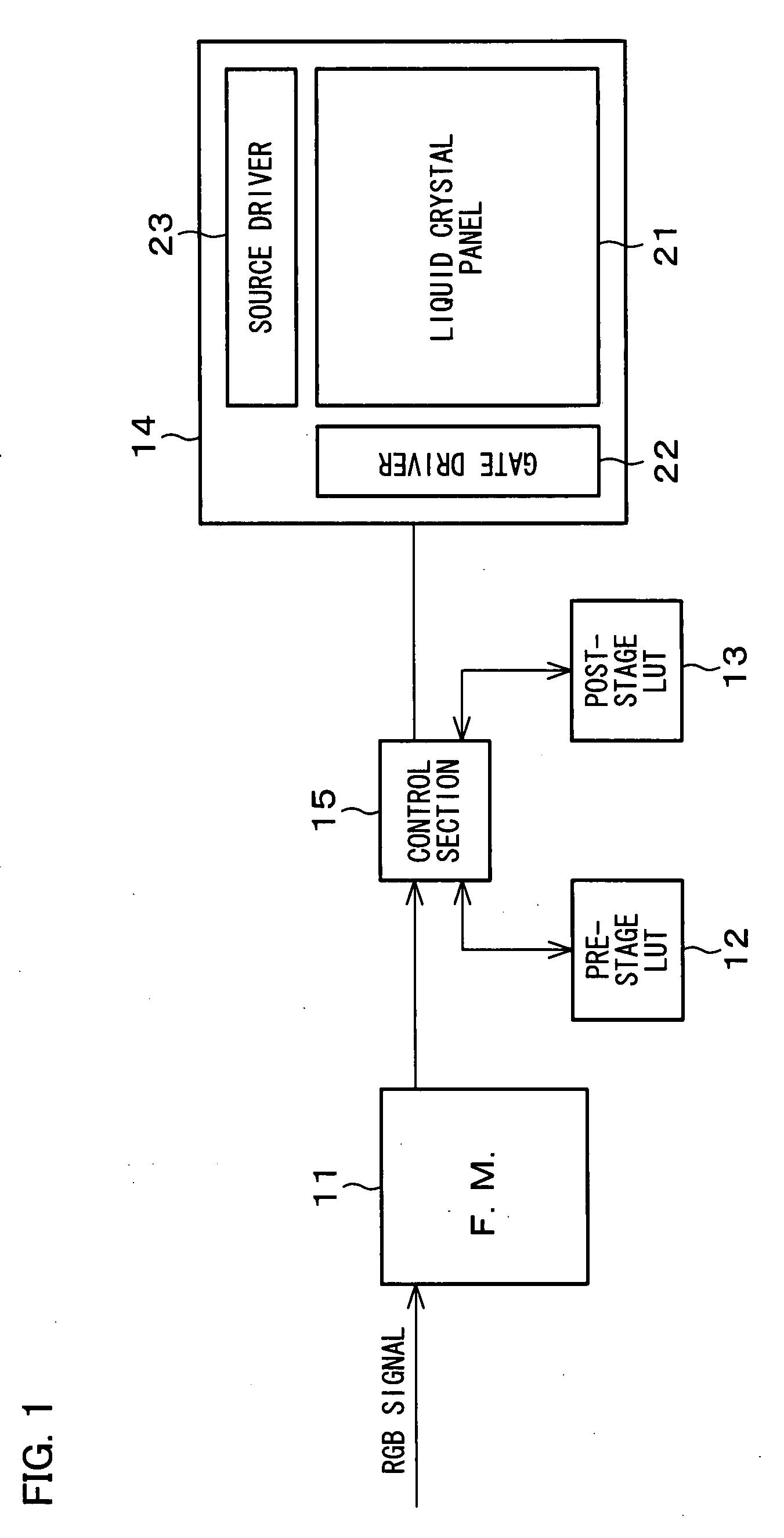
[0113]FIG. 1 is a block diagram illustrating the internal structure of the present display device. As shown in the figure, the present display device includes a frame memory (F.M.) 11, a pre-stage LUT 12, a post-stage LUT 13, a display section 14, and a control section 15.

[0114]The frame memory (image signal feeder section) 11 stores a frame of image signals (RGB signals) fed from an external signal source. The pre-stage LUT (look-up table) 12 and the post-stage LUT 13 is an association table (conversion table) between external image signal inputs and display signal outputs to the display ...


PUM


Abstract

A display device displaying an image by dividing each frame into subframes. A display section has pixels each containing a first subpixel (SP1) and a second subpixel (SP2) which are connected to the same source line (S) and the same gate line (G). A difference is created between the luminance of the first subpixels and the luminance of the second subpixels. Either the first or the second subpixels are driven for black (white) display, and the luminances of the other subpixels is adjusted, to display a low (high) luminance image. Thus, the discrepancy between the display luminance of either the first or the second subpixels and the actual luminance is minimized for improved viewing angle characteristics. The relationship between the levels of the luminances of the first and second subpixels (SP1, SP2) is changed every period. A user is less likely to see a screened pattern of bright dots and dark dots.

Description

TECHNICAL FIELD[0001]The present invention relates to display devices which display images by dividing each frame into a plurality of subframes.BACKGROUND ART[0002]An increasing number of liquid crystal displays, especially, color liquid crystal displays with a TN (Twisted Nematic) liquid crystal display panel (TN-mode liquid crystal panel, TN panel) are being used in recent years in what has been traditionally the fields for CRTs (cathode ray tubes).[0003]For example, Patent Document 1 discloses a liquid crystal display switching between TN panel driving methods according to whether the display image is a moving image or a still image.[0004]These TN panels have some problems associated with viewing angle characteristics when compared to CRTs.[0005]Grayscale characteristics change with an increasing line-of-sight angle (angle at which the panel is viewed; angle between the normal to the panel and the direction in which the panel is viewed). At some angles, grayscale inversion may oc...

Claims


Application Information

Patent Timeline
IPC IPC(8): G09G3/36G09G5/02
CPCG02F2001/134345G09G3/2022G09G2320/0673G09G3/3648G09G2320/0626G09G3/3614G02F1/134345
Inventor TOMIZAWA, KAZUNARIMORI, TOMOHIKO
Owner SHARP KK
Why Eureka
Try Eureka