
View angle control element and display device provided with the same

a control element and display device technology, applied in non-linear optics, instruments, optics, etc., can solve the problems of high production cost, display on the screen cannot be seen from a lateral direction, and the total thickness of the display device increases, so as to achieve the effect of not degrading the image quality

Inactive Publication Date: 2010-06-17
SHARP KK
View PDF1 Cites 80 Cited by
  • Summary
  • Abstract
  • Description
  • Claims
  • Application Information

AI Technical Summary

Benefits of technology

[0019]According to the present invention, a view angle control element capable of controlling a view angle without degrading image quality (front quality) when seen from a front side, and a display device provided with the view angle control element can be provided.

Problems solved by technology

Such a demand is a problem common to any display as well as a liquid crystal display.
However, according to the configuration using a liquid crystal panel for controlling a view angle as described in Documents 1 and 2, there is a problem that the total thickness of the display device increases.
Further, since it is necessary to produce and attach a liquid crystal panel for controlling a view angle, there also is a problem of a high production cost.
Therefore, when the privacy filter is attached to the screen of a display device, the display on the screen cannot be seen from a lateral direction.

Method used


Image

  • View angle control element and display device provided with the same
  • View angle control element and display device provided with the same
  • View angle control element and display device provided with the same

Examples


embodiment 1

[0048]Hereinafter, a liquid crystal display device according to Embodiment 1 of the present invention will be described with reference to the drawings. Herein, as an example of the display device according to the present invention, a configuration in which a liquid crystal display device is provided as an image display device will be illustrated.

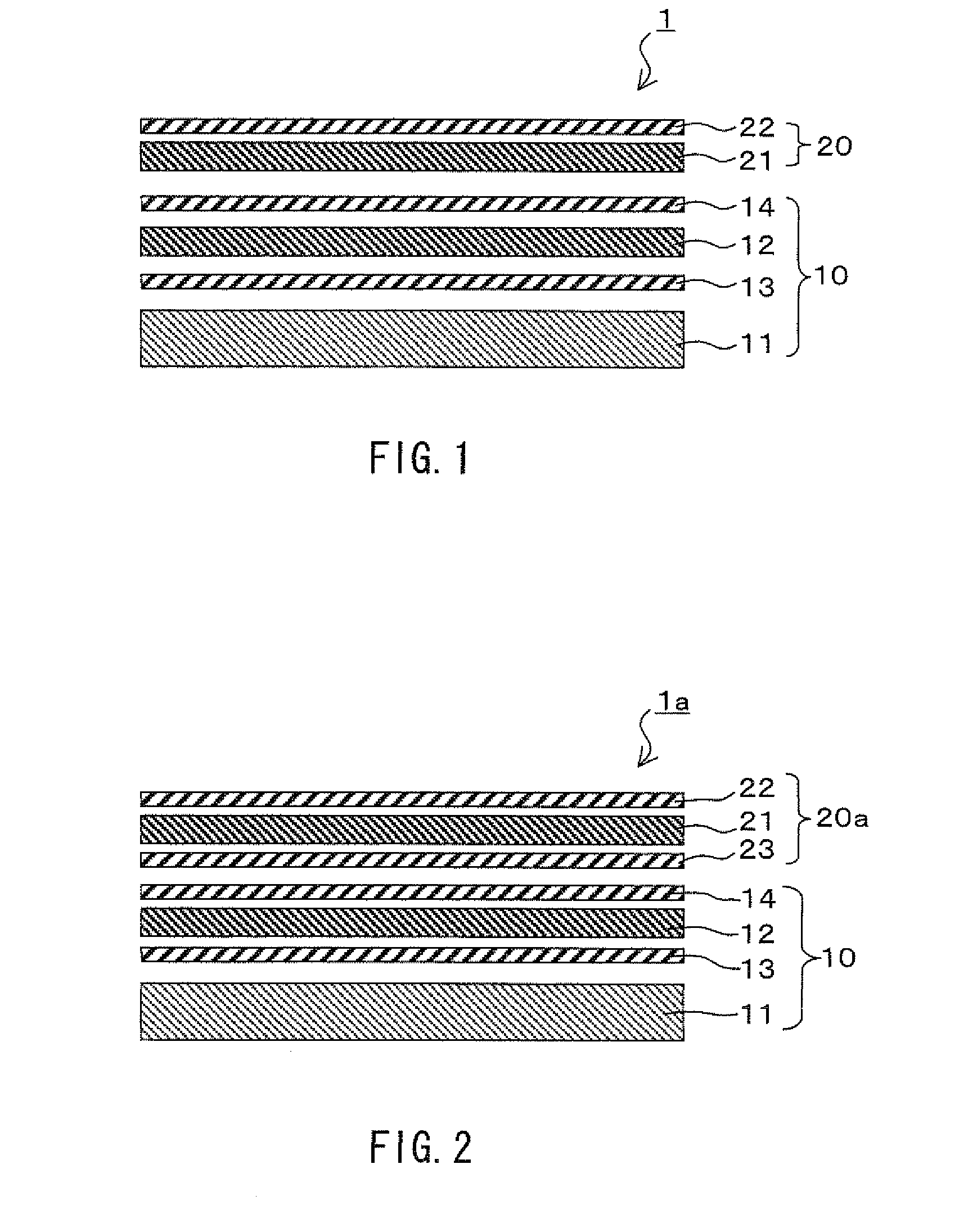
[0049]FIG. 1 is a schematic cross-sectional view showing a schematic configuration of a liquid crystal display device 1 according to Embodiment 1 of the present invention. FIG. 1 intends to show the lamination order of main constituent members of the liquid crystal display device 1 according to Embodiment 1, instead of showing an actual cross-sectional configuration.

[0050]As shown in FIG. 1, the liquid crystal display device 1 includes a liquid crystal panel 10 (image display device) that displays an image, and a view angle control film 20 (view angle control element) that is placed on a viewer side with respect to the liquid crystal panel 1...

embodiment 2

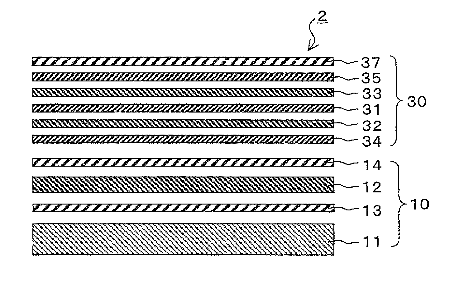
[0077]A liquid crystal display device 2 according to Embodiment 2 of the present invention will be described below. The configurations having the same functions as those of the configurations described in Embodiment 1 are denoted with the same reference numerals as those therein, and the descriptions thereof will be omitted.

[0078]As shown in FIG. 9, the liquid crystal display device 2 according to Embodiment 2 includes a view angle control film 30 instead of the view angle control film 20 of the liquid crystal display device 1 according to Embodiment 1. The view angle control film 30 has a configuration in which λ / 4 phase difference plates 32, 33, λ / 2 phase difference plates 34, 35, and a linearly polarizing plate 37 are attached to each other so as to sandwich a negative C plate 31. The lamination order of these constituent members from the liquid crystal panel 10 side is as follows: the λ / 2 phase difference plate 34, the λ / 4 phase difference plate 32, the negative C plate 31, the ...


PUM

PropertyMeasurementUnit
crossing angleaaaaaaaaaa
angleaaaaaaaaaa
azimuth angle δ3aaaaaaaaaa

Abstract

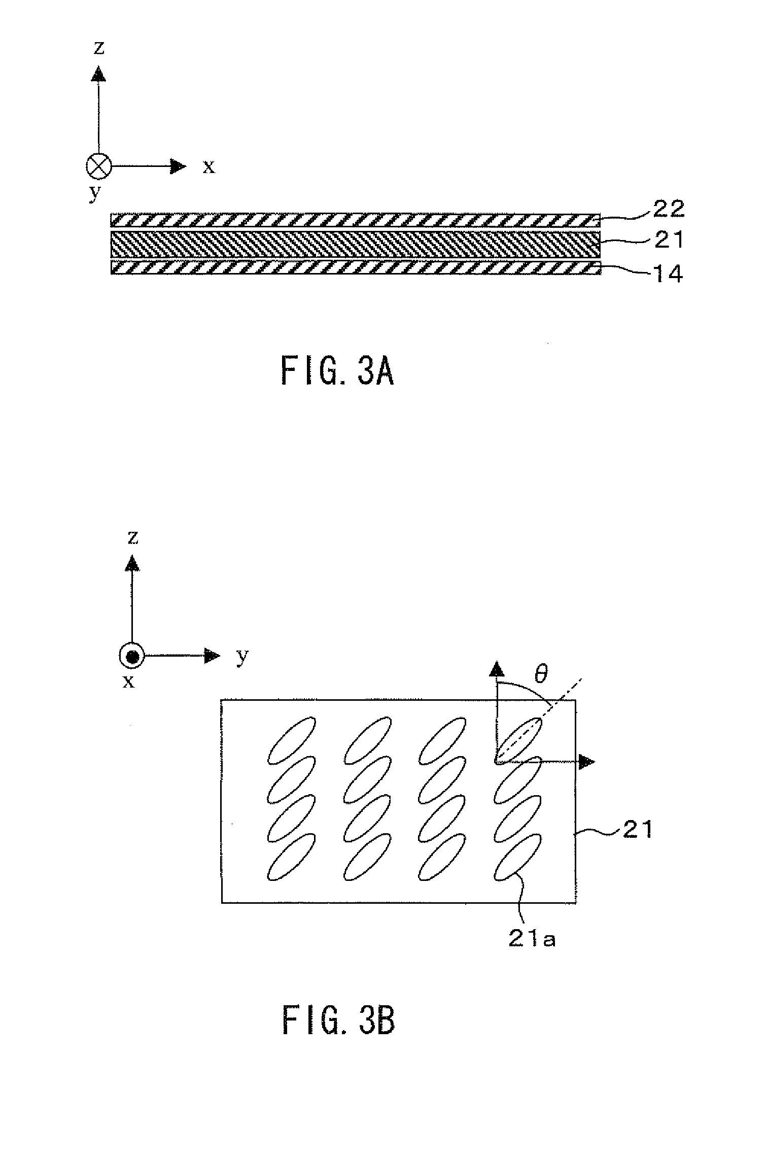
A view angle control element capable of limiting a view angle without degrading image quality (front quality) when seen from a front side and a display device provided with the view angle control element are provided. A liquid crystal display device (1) includes a liquid crystal panel (10), and a view angle control film (20) that controls a view angle of the liquid crystal panel (10). The view angle control film (20) is a laminated film including at least a liquid crystal film (21) and a linearly polarizing plate (22). In the liquid crystal film (21), liquid crystal molecules are solidified while being aligned with major axes tilted in a predetermined azimuth angle direction from a normal direction of a film surface. The linearly polarizing plate (22) of the view angle control film (20) and the linearly polarizing plate (14) of the liquid crystal panel (10) are placed so that polarization transmission axes thereof cross a major axis direction of the liquid crystal molecules when seen from the normal direction.

Description

TECHNICAL FIELD[0001]The present invention relates to a view angle control element capable of controlling a view angle and a display device provided with the view angle control element.BACKGROUND ART[0002]In general, a display is required to have the largest possible view angle so that a clear image can be seen from any visual angle. Particularly, in a liquid crystal display that is recently diffused widely, liquid crystal has view angle dependence, and hence, various technological developments have been performed with respect to the enlargement of a view angle. However, a smaller view angle, which allows only a user to identify display contents visually, may be convenient depending upon the use environment. In particular, there is a high possibility that a notebook personal computer, a personal digital assistance (PDA), a mobile telephone, or the like is used in a place such as a train or an airplane where an indefinite number of people may be present. In such a use environment, si...

Claims


Application Information

Patent Timeline
Patent Type & Authority Applications(United States)
IPC IPC(8): G02F1/1347G02F1/13
CPCG02F1/133528G02F1/13363G02F2001/133531G02F2001/133633G02F2413/105G02F2413/04G02F2413/07G02F2413/08G02F2001/133638G02F1/133531G02F1/133633G02F1/133638
Inventor YABUTA, KOJITAKATANI, TOMOOFUKUSHIMA, HIROSHI
Owner SHARP KK
Learn More