
Inter-Access Network Handover

a technology of inter-access network and handover, applied in the direction of wireless network protocol, wireless commuication services, electrical equipment, etc., can solve the problems of mobile nodes likely to face all of the delays, reduce the chances of handover, reduce the delay of handover, and reduce packet loss

Active Publication Date: 2010-06-17
UNILOC 2017 LLC
View PDF25 Cites 23 Cited by
  • Summary
  • Abstract
  • Description
  • Claims
  • Application Information

AI Technical Summary

Benefits of technology

"The present invention provides a method for facilitating network layer handover of a mobile node in a wireless network environment. The method involves receiving a router advertisement from a second access network, which advertisement includes a network-layer address of a target mobility agent in the second access network. The mobile node then forwards the network-layer address to the serving mobility agent, which in turn communicates with the target mobility agent to initiate the handover preparation. The mobile node can also use the QoS routing protocol to advertise the presence of mobility agents in the second access network and the target mobility agent can use this information to determine if the second access network can provide the same or a similar QoS to the ongoing session of the mobile node. This reduces the chances of handover to a network that cannot meet the requested QoS. The method also allows for the forwarding of additional data in the router advertisement to the serving mobility agent, which can be useful in establishing communication with the target mobility agent. Overall, the method improves the speed and efficiency of network layer handover and reduces delays in the mobile network."

Problems solved by technology

For example, if the mobile node moves out if signal coverage at the physical layer of the first access network before sending the network-layer address, the mobile node is likely to face all of the delays.

Method used


Image

  • Inter-Access Network Handover
  • Inter-Access Network Handover
  • Inter-Access Network Handover

Examples


Embodiment Construction

)

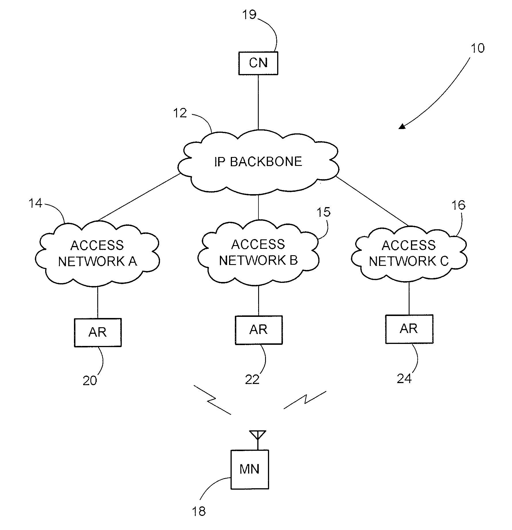
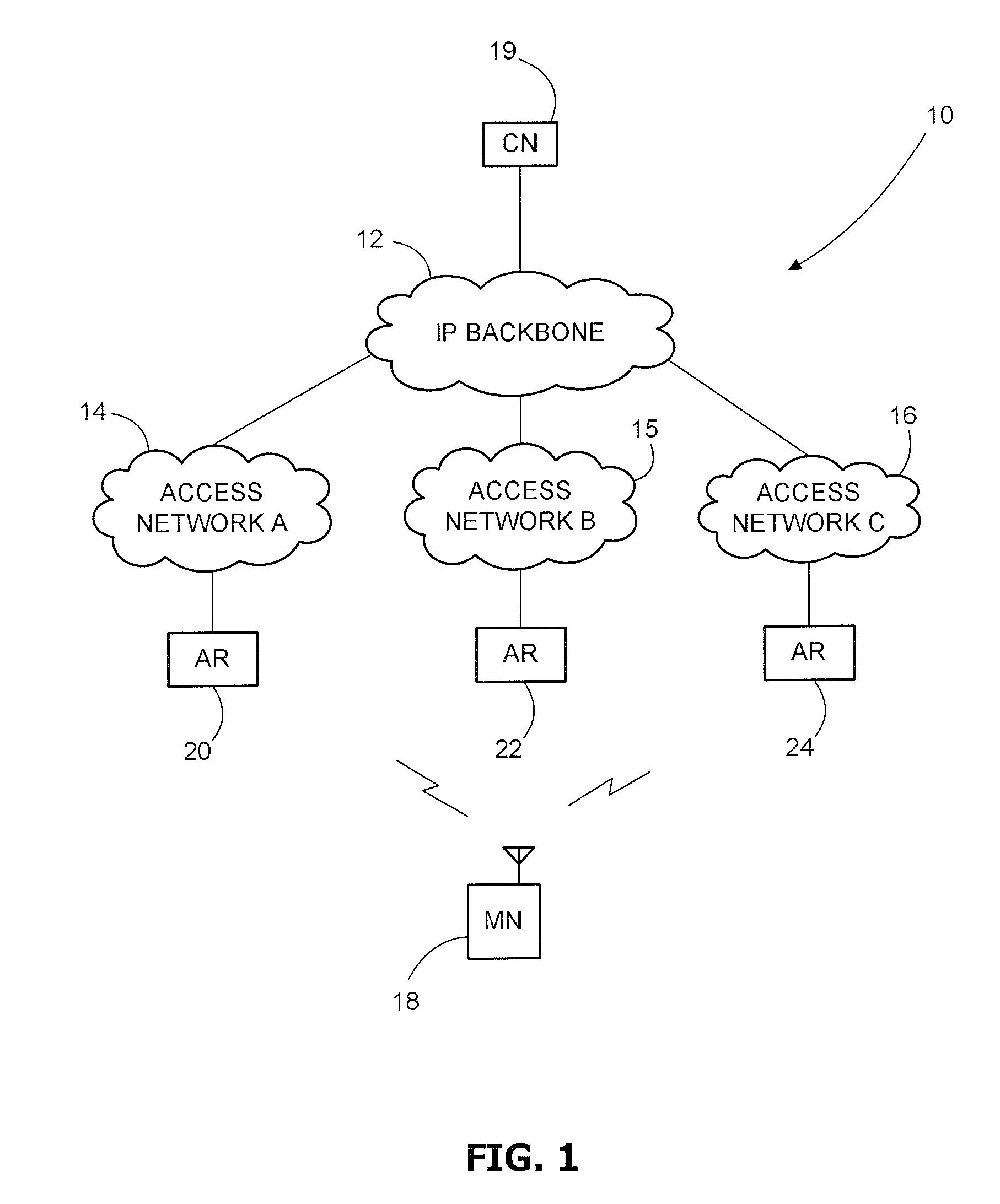
[0058]Referring to FIG. 1 an IP-based (IPv4 or IPv6 or a mixture thereof may be used in any of the networks mentioned herein) network environment generally identified by reference numeral 10 comprises an IP backbone 12 having a number of interconnected routers that provide access for network nodes to data and services stored on remote servers for example. As such the IP backbone 12 may form part of the Internet. In this embodiment any three IP-based access networks 14, 15, 16 provide access for a wireless mobile node (MN) 18 to the IP backbone 12, although there may be any number of access networks and mobile nodes of course. The access networks 14, 15, 16 may be an IP-based cellular network (such as 3GPP Release 5 or 6, UMTS Long Term Evolution (LTE) or any future IP-enabled cellular network) or the combination of an ISP and a number of WLAN routers for example. Access to the IP backbone 12 enables the MN 18 to communicate with a correspondent node (CN) 19. The CN 19 may be a medi...


PUM


Abstract

In a wireless network environment comprising first and second packet-switched access networks, each access network using a tunnelling-type micro-mobility protocol and a Quality of Service (QoS) routing protocol to route packet data to and from mobile nodes attached thereto, and each access network comprising an access router to which a mobile node may attach, a mobility agent with which said mobile node may register and a gateway, a method of facilitating network layer handover of said mobile node from said first access network to said second access network, said mobile node registered in said first access network with a serving mobility agent, which method comprises the steps of: said mobile node receiving a router advertisement from said second access network, which router advertisement comprises a network-layer address of a target mobility agent in said second access network with which said mobile node may register; and said mobile node forwarding said network-layer address to said serving mobility agent, whereby said serving mobility agent may communicate with said target mobility agent to facilitate network-layer handover of said mobile node to said second access network.

Description

CROSS REFERENCE TO RELATED APPLICATION(S)[0001]This application claims foreign priority to United Kingdom Patent Application Serial Number 08 228 14.0 filed Dec. 15, 2008, the entire disclosure of which is herein incorporated by reference.FIELD OF THE INVENTION[0002]The present invention relates to a method facilitating network layer handover of a mobile node between access networks that use a tunnelling-type micro-mobility protocol and a Quality of Service (QoS) routing protocol, to a packet-switched wireless access network for taking part in the method, to various routers for use in the method, to a mobile node for use in the method, and to a method of manufacturing such a mobile node.BACKGROUND TO THE INVENTION[0003]Many different requirements are expected of the network layer in all-IP access networks (e.g. 4G cellular networks). Two in particular are mobility and QoS. The former enables users to communicate seamlessly with remote network nodes via the Internet wherever they are...

Claims


Application Information

Patent Timeline
Patent Type & Authority Applications(United States)
IPC IPC(8): H04W36/00
CPCH04W36/0016H04W80/04H04W36/14H04W36/0044H04W36/322H04W36/302H04W36/0061H04W36/22H04W60/04
Inventor AGHVAMI, ABDOL HAMIDPANGALOS, PAUL ANTHONYAUDSIN, DEV PRAGAD
Owner UNILOC 2017 LLC
Learn More