
Selective peak power reduction

Active Publication Date: 2010-06-17
BLACKBERRY LTD
View PDF8 Cites 33 Cited by
  • Summary
  • Abstract
  • Description
  • Claims
  • Application Information

AI Technical Summary

Benefits of technology

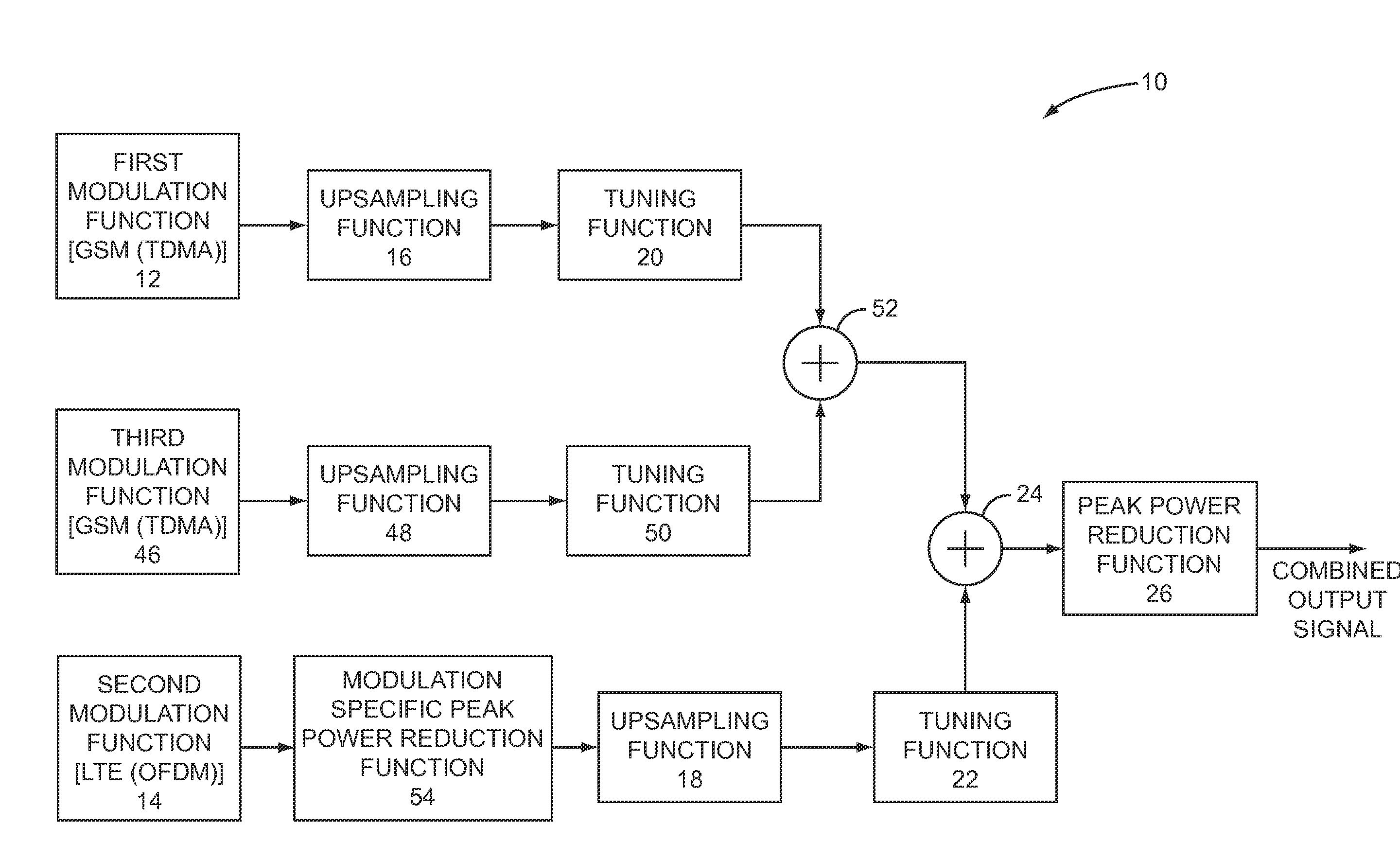
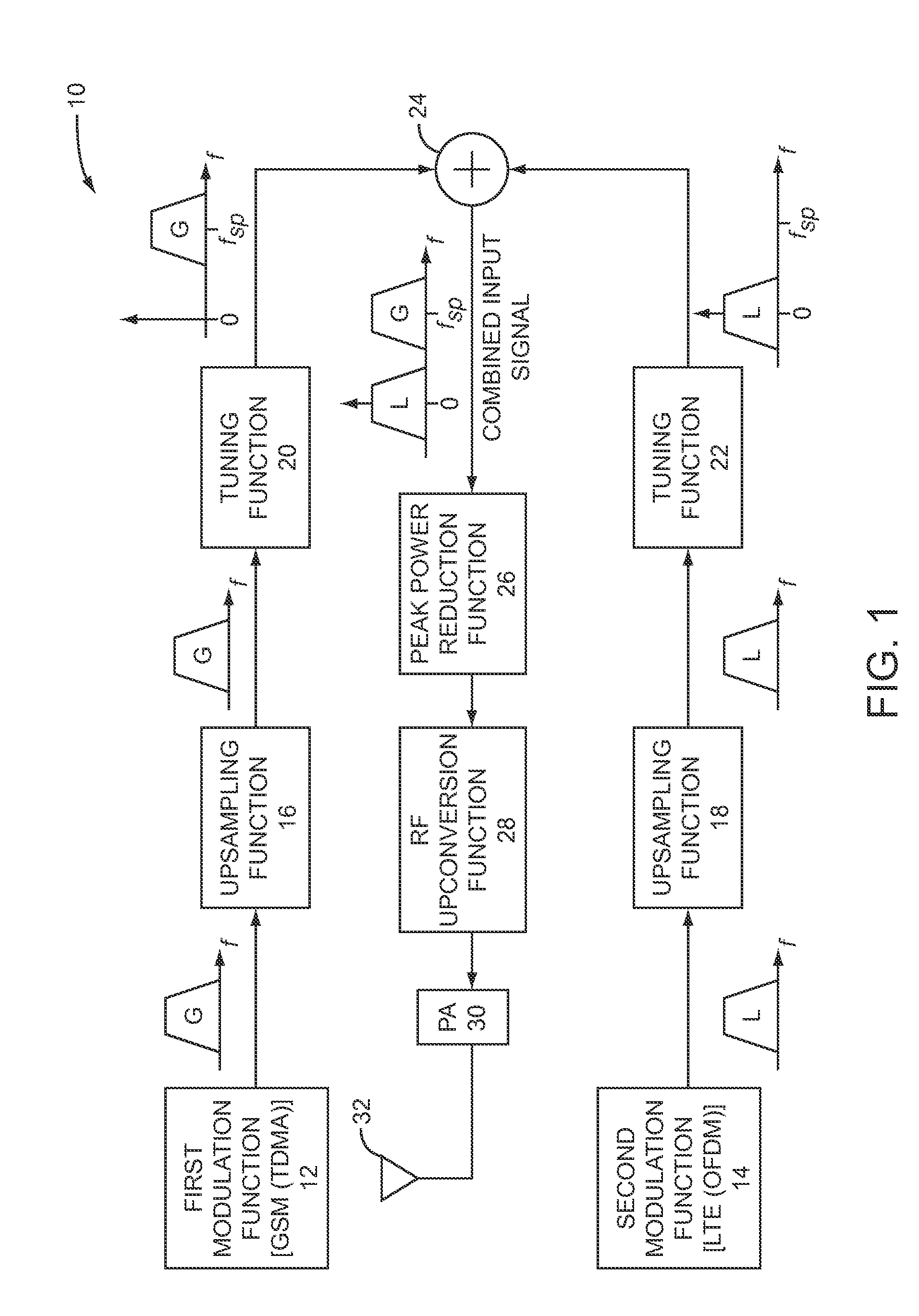
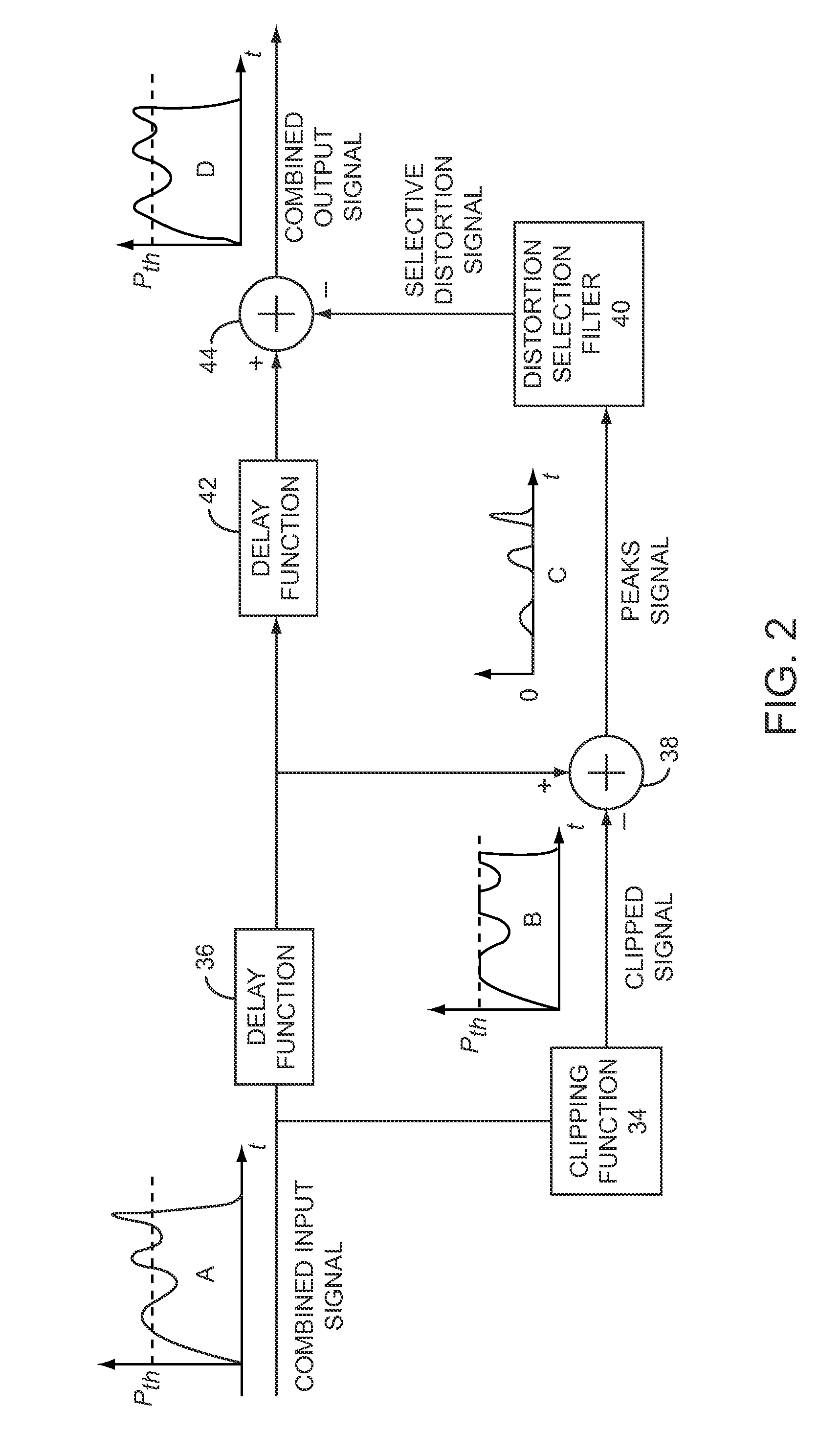
[0008]The present invention provides a technique for reducing the peak power of a combined signal that has a first signal of a first modulation type and a second signal of a second modulation type. Based on the combined signal, peak reduction distortion is determined. The peak reduction distortion is configured such that, if applied to the entirety of the combined signal, excessive peaks throughout the combined signal would be reduced. However, instead of applying the entirety of the peak reduction distortion, a selected portion of the peak reduction distortion is applied to a corresponding portion of the combined signal to reduce the peak power of the combined signal.

Problems solved by technology

Generally, a lower PAPR enables a higher amplifier efficiency, whereas a higher PAPR results in lower amplifier efficiency.
OFDM systems, such as the Third Generation Partnership Project's (3GPP's) Long Term Evolution (LTE) standard and the World Wide Interoperability for Microwave Access (WiMAX) standard, employ a number of independently modulated sub-carriers, which can result in high PAPRs.
Unfortunately, when the different signals from different modulation schemes are combined, the PAPR associated with the combined input signal can significantly increase.
Even if corresponding PAPR reduction techniques are individually applied to each of the different signals before the respective signals are combined, the combined input signal will still have an undesirable PAPR.
Further, application of existing PAPR techniques to such a combined signal have proven ineffective, primarily because the different types of signals in the combined signal require different PAPR techniques, or one type of signal is intolerant to the PAPR techniques required by another type of signal.

Method used


Image

  • Selective peak power reduction
  • Selective peak power reduction
  • Selective peak power reduction

Examples


Embodiment Construction

[0022]The embodiments set forth below represent the necessary information to enable those skilled in the art to practice the invention and illustrate the best mode of practicing the invention. Upon reading the following description in light of the accompanying drawing figures, those skilled in the art will understand the concepts of the invention and will recognize applications of these concepts not particularly addressed herein. It should be understood that these concepts and applications fall within the scope of the disclosure and the accompanying claims.

[0023]The present invention provides a technique for reducing the peak power of a combined signal that has a first signal of a first modulation type and a second signal of a second modulation type. Based on the combined signal, peak reduction distortion is determined. The peak reduction distortion is configured such that, when applied to the entirety of the combined signal, excessive peaks throughout the combined signal would be r...


PUM


Abstract

The present invention provides a technique for reducing the peak power of a combined signal that has a first signal of a first modulation type and a second signal of a second modulation type. Based on the combined signal, peak reduction distortion is determined. The peak reduction distortion is configured such that, if applied to the entirety of the combined signal, excessive peaks throughout the combined signal would be reduced. However, instead of applying the entirety of the peak reduction distortion, a selected portion of the peak reduction distortion is applied to a corresponding portion of the combined signal to reduce the peak power of the combined signal.

Description

FIELD OF THE INVENTION[0001]The present invention relates to peak power reduction, and in particular to selective peak power reduction.BACKGROUND OF THE INVENTION[0002]A peak-to-average power ratio (PAPR) is a measure of instantaneous peak power relative to the average power being supplied by a power amplifier when amplifying a given input signal to provide an amplified output signal. The PAPR has an impact on amplifier efficiency, which is invariably an important attribute of portable communication systems that rely on battery power. More efficient amplifiers require less energy to amplify a given signal to a certain level than less efficient amplifiers. Generally, a lower PAPR enables a higher amplifier efficiency, whereas a higher PAPR results in lower amplifier efficiency. Accordingly, designers are constantly trying to build more efficient communication systems that result in lower PAPRs.[0003]The PAPR for communication systems is typically a function of the input signal being ...

Claims


Application Information

Patent Timeline
IPC IPC(8): H04L27/28H04B1/10H04L25/49
CPCH04L25/49Y02B60/50H04L27/2624H03L5/02H04B1/04
Inventor MORRIS, BRADLEY JOHNFULLER, ARTHUR THOMAS GERALD
Owner BLACKBERRY LTD
Learn More