Camera module

a technology of camera module and camera body, which is applied in the field of camera module, can solve the problems of cumbersome process of adjusting and managing the amount of adhesive and curing conditions, cumbersome assembly process, and reducing costs, so as to achieve the effect of reducing costs and considerably simplifying the assembly process

Inactive Publication Date: 2010-06-17
SONY CORP
View PDF17 Cites 63 Cited by
  • Summary
  • Abstract
  • Description
  • Claims
  • Application Information

AI Technical Summary

Benefits of technology

[0008]Thus, according to the present invention, the inner barrel and the outer barrel are clamped in the optical-axis direction by using the retaining plate. Therefore, it is not necessary to adjust and manage the amount of adhesive and curing conditions. In addition, the curing time for the adhesive is also not necessary. Therefore, the assembly process can be considerably simplified and it is advantageous in reducing costs.

Problems solved by technology

In the camera module according to the related art, since the two front and rear barrel members are adhered to each other with an adhesive, a cumbersome process of adjusting and managing the amount of adhesive and curing conditions is necessary.
Therefore, the assembly process is cumbersome and it is disadvantageous in reducing costs.

Method used


Image

  • Camera module
  • Camera module
  • Camera module

Examples


Embodiment Construction

[0061]First, a first reference example will be described before describing an embodiment of the present invention.

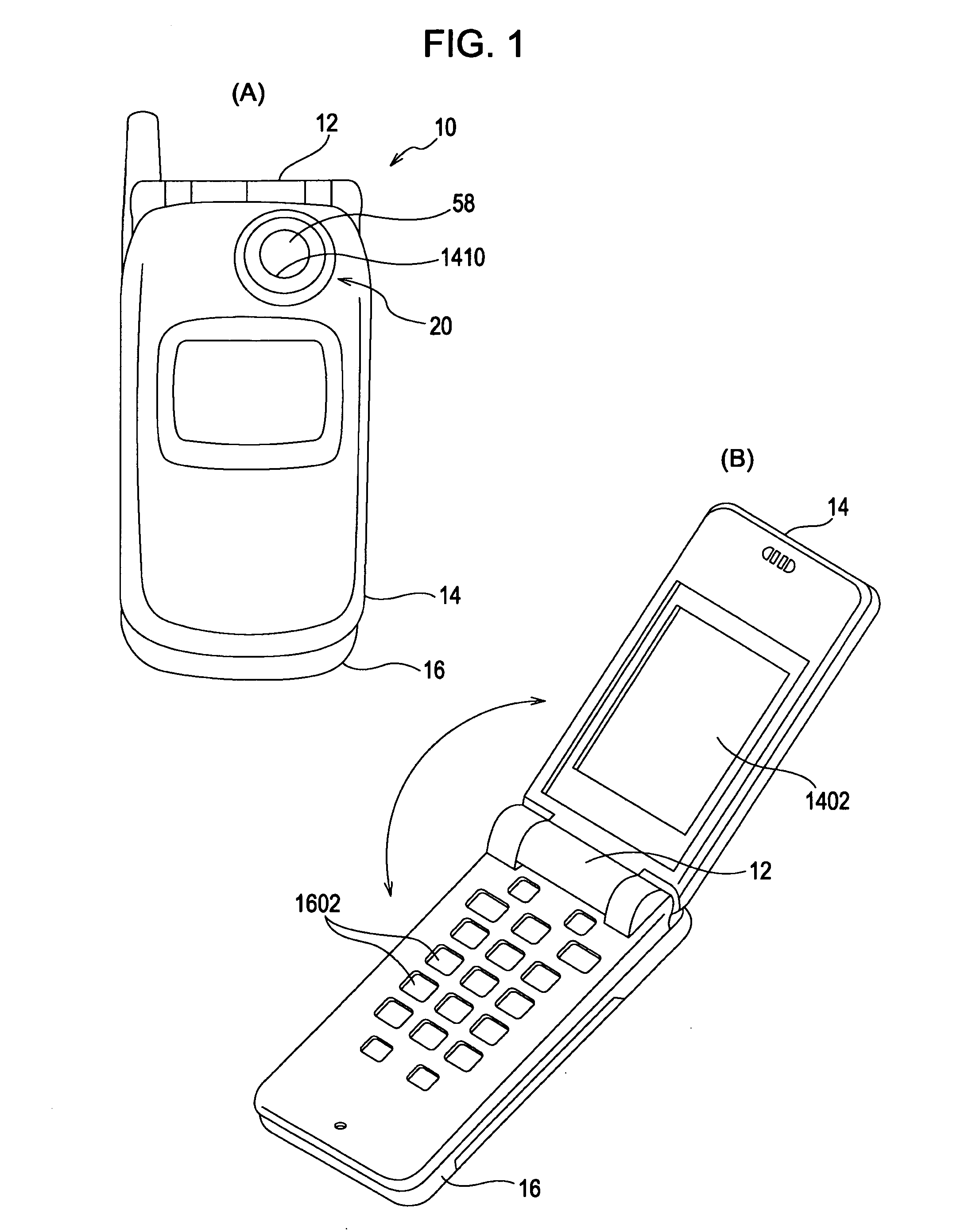
[0062]In FIG. 1, (A) and (B) are external views illustrating an example of an electronic apparatus in which an image pickup device 20 having a camera module 22 according to the first reference example is installed.

[0063]As shown in FIG. 1, an electronic apparatus 10 is a portable phone and includes first and second housings 14 and 16 which are pivotally connected to each other with a hinge unit 12.

[0064]A liquid crystal display panel 1402 is provided on the inner surface of the first housing 14, and operation switches 1602, such as numeric keys and function keys, are provided on the inner surface of the second housing 16.

[0065]The image pickup device 20 is installed in a base-end section of the first housing 14 and is structured such that an image picked up by the image pickup device 20 is displayed on the liquid crystal display panel 1402.

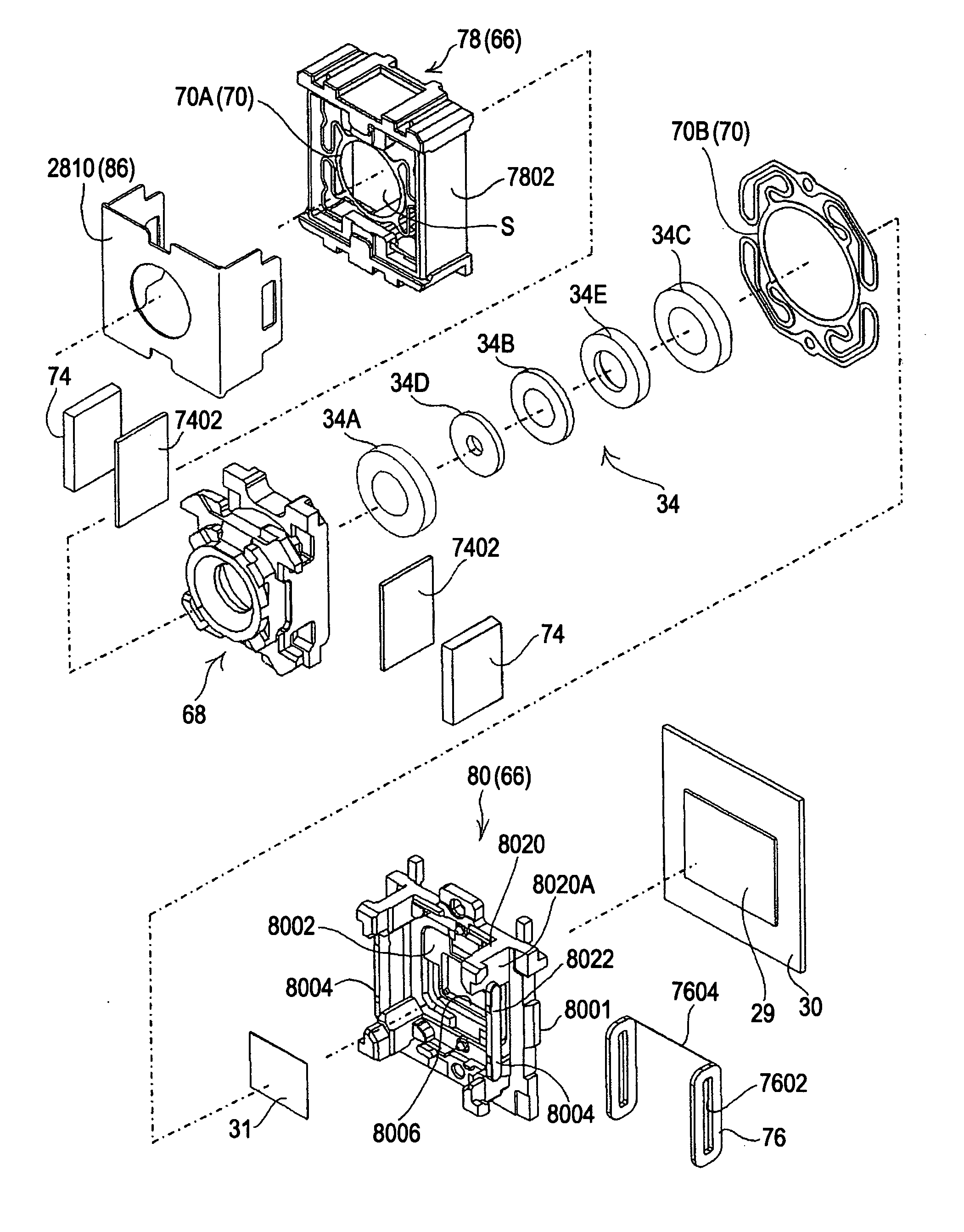
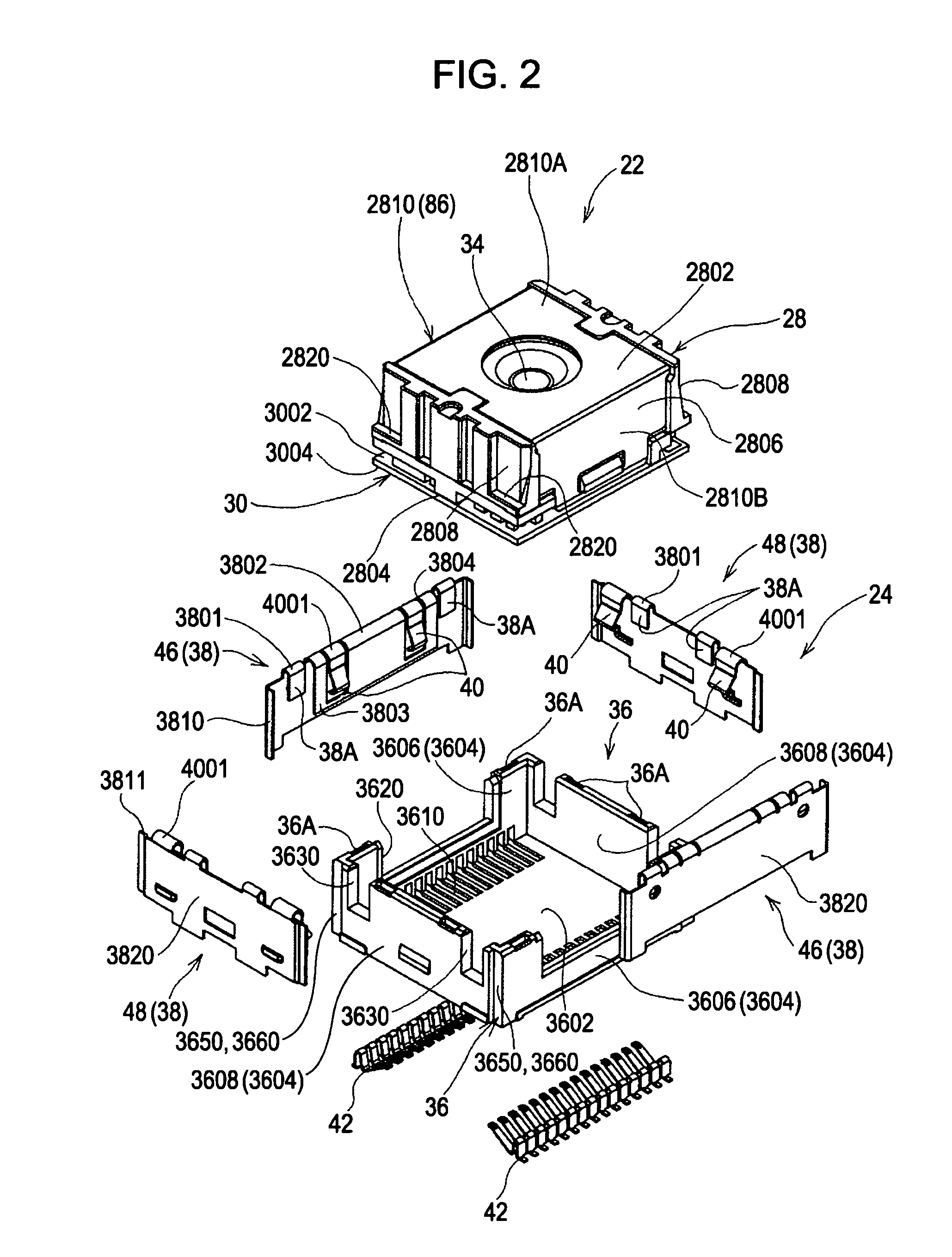
[0066]FIG. 2 is an exploded per...


PUM


Abstract

A camera module advantageous in simplifying an assembly process is provided. A camera module 22 includes a barrel unit 66 having a housing space S; a lens holding unit 68 which holds an imaging optical system 34, which is housed in the housing space S, and which is supported such that the lens holding unit 68 is movable along an optical axis of the imaging optical system 34; an image pickup element 29 which is disposed in the barrel unit 66 and which picks up an object image guided by the imaging optical system 34; and a driving unit 72 which moves the lens holding unit 68 along the optical axis of the imaging optical system 34. The barrel unit 66 includes an inner barrel 80 in which the housing space S is formed and an outer barrel 78 disposed outside the inner barrel 80. A retaining plate 86 includes a front plate portion 86A and two side plate portions 86B. The retaining plate 86 clamps the inner barrel 80 and the outer barrel 78 in the optical axis direction in the state in which the front plate portion 86A retains a front end of the outer barrel 78 and distal ends of the two side plate portions 86B retain the rear end-face wall 8002.

Description

TECHNICAL FIELD [0001]The present invention relates to, for example, a camera module installed in a portable electronic apparatus or the like.BACKGROUND ART[0002]Recently, electronic apparatuses, such as portable phones or PDA (Personal Digital Assistants), in which camera modules are installed have been provided.[0003]A camera module includes a lens holding unit which holds an imaging optical system, a barrel unit which houses the lens holding unit, an image pickup element which picks up an object image guided by the imaging optical system, and a driving unit which causes the lens holding unit to move along an optical axis.[0004]As an example of such a camera module, a camera module in which the barrel unit includes two front and rear barrel members and in which the front and rear barrel members are fixed to each other with an adhesive has been proposed (Japanese Unexamined Patent Application Publication No. 2006-227103).[0005]In the camera module according to the related art, sinc...

Claims


Application Information

Patent Timeline
Patent Type & Authority Applications(United States)
IPC IPC(8): G03B17/02
CPCG02B7/102G03B17/02G03B2217/002H04N5/2257H04M1/0264H04N5/2253H04N5/2254H04M1/0214H04N23/57H04N23/55H04N23/54H04N23/00
Inventor IMAI, SATOSHIICHIKAWA, MITSURUKANAI, FUJIOHORIDAN, ATSUSHIOKABE, TAKAHIRO
Owner SONY CORP
Why Eureka
Try Eureka