Battery stack arrangement

Active Publication Date: 2010-06-17
NILAR INT AB
View PDF4 Cites 27 Cited by
  • Summary
  • Abstract
  • Description
  • Claims
  • Application Information

AI Technical Summary

Benefits of technology

[0006]The object with the present invention is to provide a stack arrangement for a bipolar battery wherein an internal

Problems solved by technology

A drawback with prior art batteries is that the amount of pressure applied over the gasket will also be more or less applied over the stacked battery components of the battery cells.
An increased pressure will result in a lower internal resistance, but there are limits to what degree the pressure may be increased without introducing other undesired effects, such as hi

Method used


Image

  • Battery stack arrangement
  • Battery stack arrangement
  • Battery stack arrangement

Examples


third embodiment

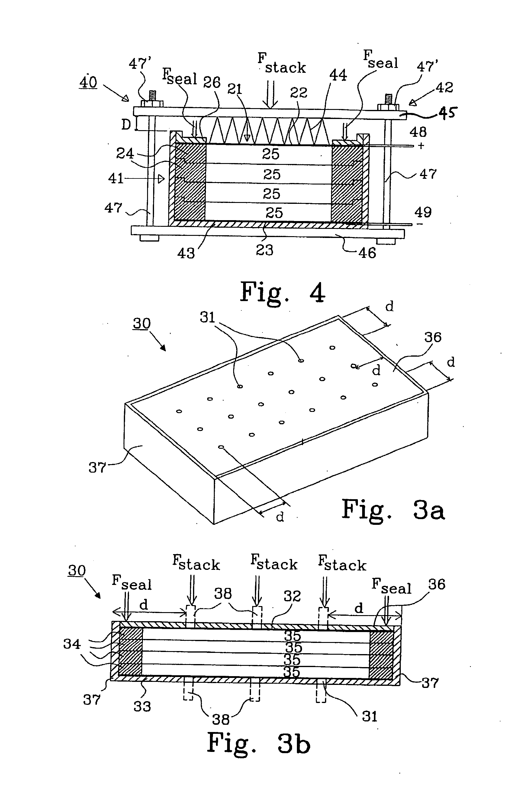
[0033]FIG. 6 shows a cross-sectional view of a battery stack arrangement 70 having two batteries 71a, 71b as described in connection with FIGS. 3a and 3b. A pin 38 is provided in each hole 31 to create a distance D on each side of the batteries 71a, 71b to permit a cooling medium to pass by, and at the same time abut against the endplates 32, 33 inside the casing. Electrodes and separators are not shown inside each cell for clarity.

[0034]A mounting frame 77 is provided around the batteries 71a and 71b, with a first mounting unit 78 and a second mounting unit 79. The frame is held in place using tie units 82, such as tie rods, but other clamping arrangements may be used. The first and second mounting units are in this embodiment preferably made from an insulating material and are resilient to be able to accommodate the variations of thickness in the electrodes during operation. A seal pressure Fseal over the gaskets 34 in each battery is created and maintained as discussed above, and...

fourth embodiment

[0036]FIG. 7 shows a schematic cross-sectional view of a battery stack arrangement 90 according to the invention. Three batteries 91a, 91b and 91c are arranged in a first battery stack and are connected in series, in a manner similar to the embodiment described in connection with FIG. 5. Furthermore, three additional batteries 92a, 92b and 92c are arranged in a second battery stack are also connected in series, in a manner similar to the embodiment described in connection with FIG. 5. A mounting frame comprising a first, second and third mounting unit 93, 94 and 95 are provided to maintain spacing elements 61 in position during operation. The first and second mounting unit 93, 94 are used for respective battery stack, but the third mounting unit 95 is used for both battery stacks. Tie units interconnect the mounting units to form the mounting frame. Furthermore, the battery stacks are connected in parallel as illustrated in the figure with the connection 96.

[0037]In a preferred embo...


PUM


Abstract

The present invention relates to a battery stack arrangement (50) comprising at least one bipolar battery. Each bipolar battery comprises a plurality of battery cell arranged between endplates (22,23). Each battery cell is provided with a seal (24) arranged around the entire periphery of each cell, and a sealing pressure Fseal is applied over the seal to prevent electrolyte leakage between adjacent cells. The battery stack arrangement further comprises a mounting frame (57) including: at least two mounting units (58,59) and at least one tie unit (60, 60′, 60″) holding said mounting units together. The bipolar battery is arranged between the mounting units (58,59), and the battery stack arrangement further comprises at least one spacing element (61) arranged between the mounting units (58,59) and each spacing element (61) abuts against at least one endplate (22,23) and is held in place by said mounting frame (57) to create a stack pressure Fstack, independent of the sealing pressure Fseal. The stack pressure is controlled by the tie unit.

Description

TECHNICAL FIELD[0001]The present invention relates to a battery stack arrangement, especially intended for bipolar batteries in hybrid vehicles.BACKGROUND TO THE INVENTION[0002]An essential feature to obtain a good performance of a bipolar battery of the type as disclosed in the published international patent application WO 2005 / 048390 is a low internal resistance between the terminals. This is achieved by applying a pressure over a plurality of battery cells using a hydrophobic gasket around the entire periphery of each battery cell to prevent electrolyte bridges to be formed between adjacent battery cells. A drawback with prior art batteries is that the amount of pressure applied over the gasket will also be more or less applied over the stacked battery components of the battery cells. Also, the internal resistance is dependent on the level of contact that exists between the battery components, and thus the magnitude of mechanical load on the battery stack. An increased pressure w...

Claims


Application Information

Patent Timeline
IPC IPC(8): H01M2/10H01M50/209H01M50/271H01M50/296H01M50/40
CPCH01M2/10H01M6/5038H01M10/0413H01M10/0418H01M10/0468H01M10/0481H01M10/5075H01M10/5016H01M10/5032H01M10/5057H01M10/5059H01M10/5067H01M10/5004H01M10/625H01M10/6563H01M10/647H01M10/6556H01M10/6557H01M10/6567H01M10/613Y02E60/10Y02P70/50H01M50/271H01M50/296H01M50/40H01M50/209
Inventor FREDRIKSSON, LARSPUESTER, NEIL H.HOWLETT, RICHARD
Owner NILAR INT AB
Why Eureka
Try Eureka