
Air tolerant implantable piston pump

a piston pump and air-tolerant technology, applied in the direction of piston pumps, positive displacement liquid engines, liquid fuel engines, etc., to achieve the effect of preventing undesired or inadvertent administration, reducing energy consumption of the drive mechanism, and avoiding inadvertent or inadvertent administration

Active Publication Date: 2010-06-17
MEDTRONIC INC
View PDF53 Cites 5 Cited by
  • Summary
  • Abstract
  • Description
  • Claims
  • Application Information

AI Technical Summary

Benefits of technology

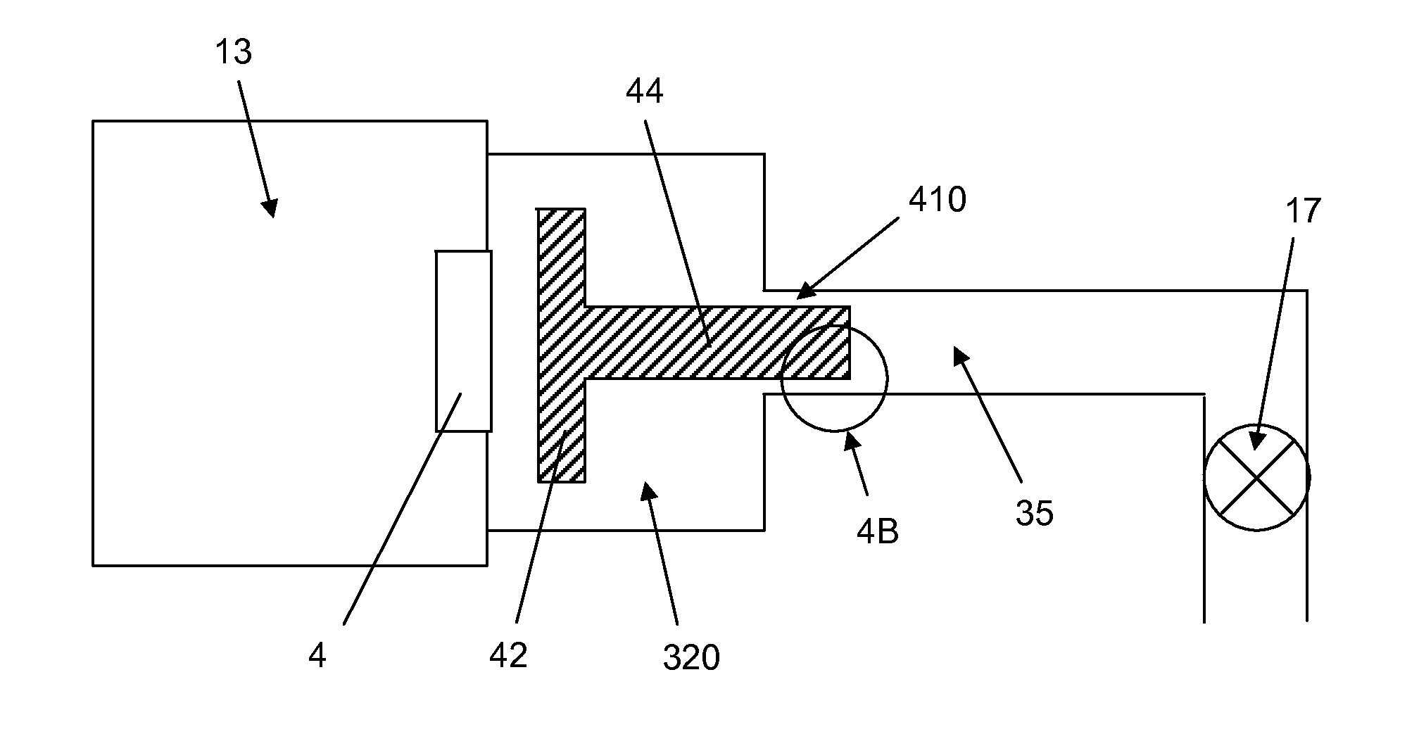
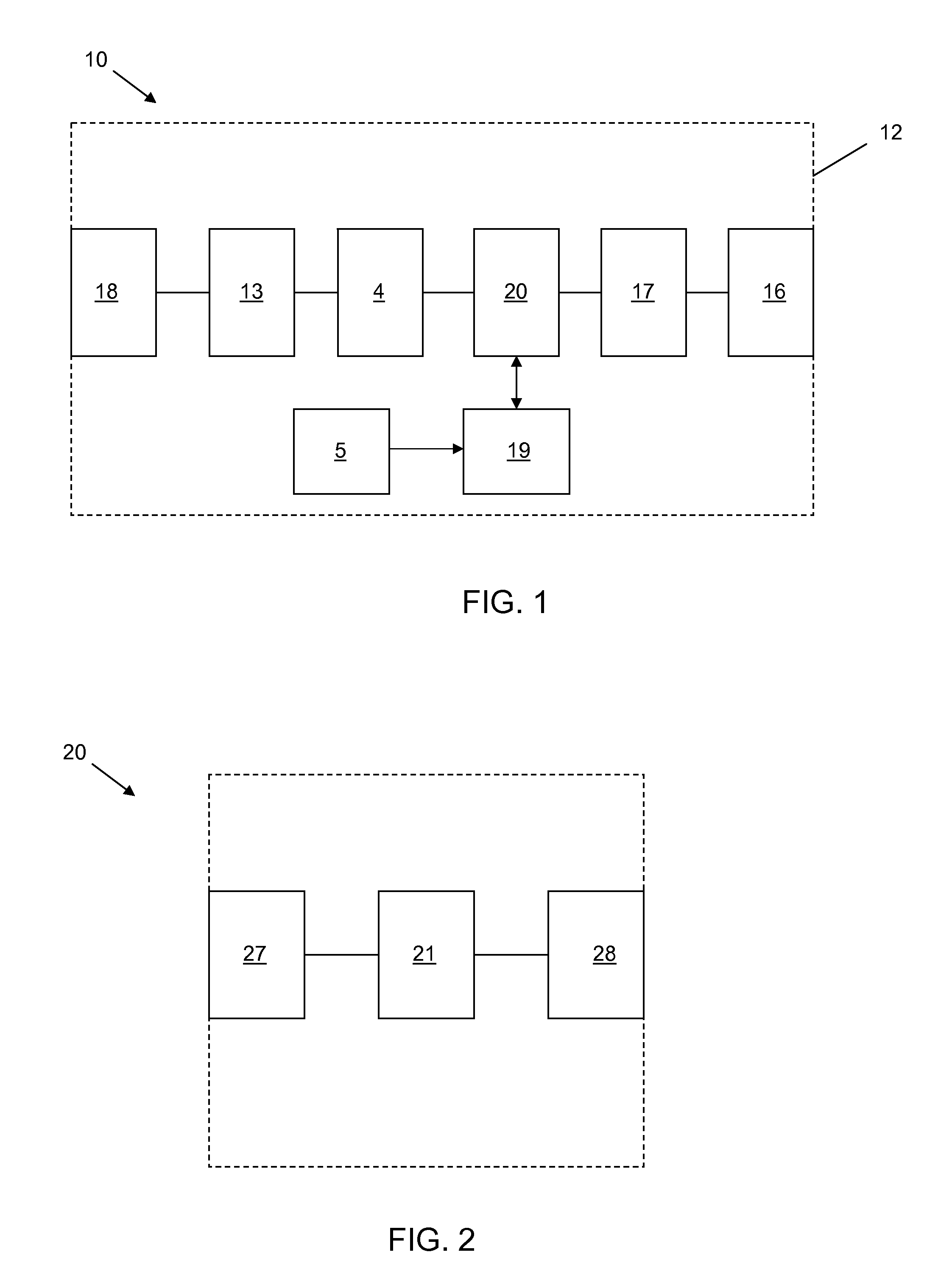
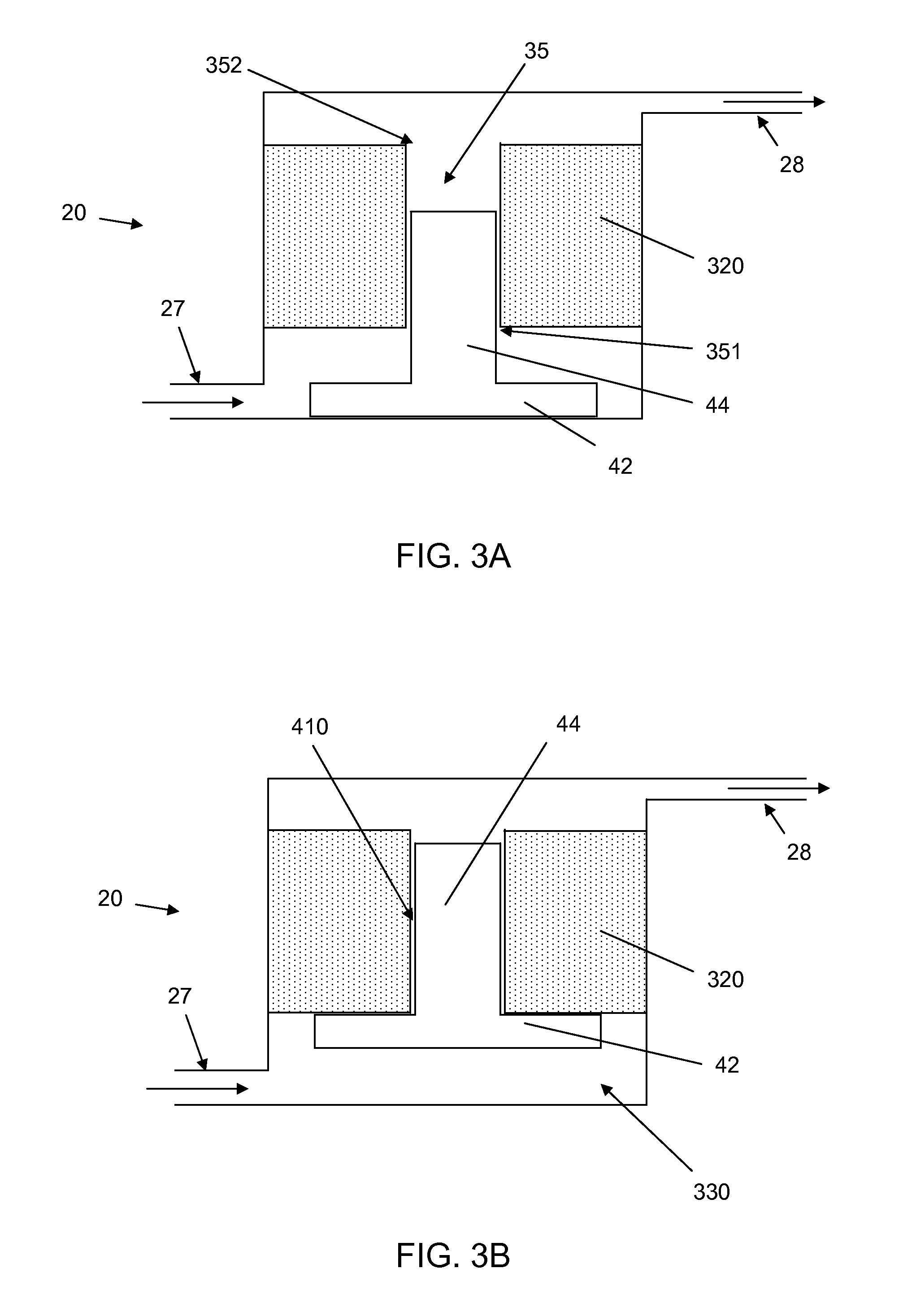
The present disclosure describes implantable infusion devices that can tolerate air bubbles and incomplete degassing of the reservoir and piston. The devices include a piston drive mechanism with a small clearance between the piston and the channel, which prevents air bubbles from passing through. The devices also have a valve downstream of the piston channel with a cracking pressure that is between the reservoir pressure and the inlet chamber pressure, which prevents inadvertent or undesired administration of infusion medium. The devices can also include a filter to prevent microorganisms from entering the inlet chamber. The devices described herein have improved safety and reliability compared to previous devices.

Problems solved by technology

If the valve fails or is of too low of a cracking pressure, therapeutic fluid may be inadvertently pushed through the device and into the patient.

Method used


Image

  • Air tolerant implantable piston pump
  • Air tolerant implantable piston pump
  • Air tolerant implantable piston pump

Examples


Embodiment Construction

[0024]In the following detailed description, reference is made to the accompanying drawings that form a part hereof, and in which are shown by way of illustration several specific embodiments of devices, systems and methods. It is to be understood that other embodiments are contemplated and may be made without departing from the scope of spirit of the present invention. The following detailed description, therefore, is not to be taken in a limiting sense.

[0025]All scientific and technical terms used herein have meanings commonly used in the art unless otherwise specified. The definitions provided herein are to facilitate understanding of certain terms used frequently herein and are not meant to limit the scope of the present disclosure.

[0026]As used in this specification and the appended claims, the singular forms “a”, “an”, and “the” encompass embodiments having plural referents, unless the content clearly dictates otherwise. As used in this specification and the appended claims, t...


PUM


Abstract

An implantable infusion device includes a reservoir for housing an infusion medium and a drive mechanism having an inlet chamber, a piston and a piston channel. The inlet chamber is in fluid communication with the reservoir. The piston channel is in fluid communication with the inlet chamber, and has a distal end and a proximal end, the proximal end being closer to the inlet channel than the distal end. The piston is axially moveable within the piston channel to drive infusion medium out of the distal end of the piston channel. The clearance between the piston and the channel is sufficiently small to prevent undissolved gas in the inlet chamber from passing through the clearance. The inlet chamber may be sufficiently large to allow undissolved gas to accumulate without adversely affecting the performance of the infusion device.

Description

RELATED APPLICATION[0001]This application is a Continuation-In-Part application of U.S. application Ser. No. 12 / 334,985, filed on Dec. 15, 2008, published as US 2009 / 0118711 on May 7, 2009, which application is incorporated herein by reference in its entirety to the extent that it does not conflict with the disclosure presented herein.FIELD[0002]The present disclosure relates generally to implantable infusion devices; in particular to implantable infusion devices employing piston drive mechanisms.BACKGROUND[0003]Treatment of diseases and ailments of the body often benefit from short- or long-term infusion of therapeutic compositions. While such therapeutic compositions may be administered extracorporeally, e.g., via transcutaneous injection, many patients benefit from the consistent and repeatable dosage provided by an implantable infusion device. Such devices may employ a reservoir for storing an infusible therapeutic composition and a pumping mechanism coupled to the reservoir for...

Claims


Application Information

Patent Timeline
Patent Type & Authority Applications(United States)
IPC IPC(8): A61M31/00
CPCA61M5/14216A61M5/14276A61M5/165A61M5/36F04B53/1032F04B17/042F04B19/006F04B35/045F04B53/008A61M2205/7518
Inventor HAASE, JAMES M.WHITEHEAD, NICHOLAS R.MEZERA, RONALD L.
Owner MEDTRONIC INC
Learn More