
System and method for data migration between computer cluster architecture and data storage devices

a computer cluster and data storage technology, applied in the direction of memory addressing/allocation/relocation, sustainable buildings, instruments, etc., can solve the problems of large computing element ratio to servers, large number of disk drives, and inability to meet random requests, so as to improve the duty cycle of computer clusters and avoid excessive power consumption of disk drives

Active Publication Date: 2010-06-17
DATADIRECT NETWORKS
View PDF36 Cites 34 Cited by
  • Summary
  • Abstract
  • Description
  • Claims
  • Application Information

AI Technical Summary

Benefits of technology

[0011]It is therefore an object of the present invention to provide a system in which data migrates between high performance computer clusters and data storage devices in an efficient manner, and wherein the improved duty cycle of the computer clusters may be attained without excessive power consumption for powering the disk drives.
[0012]It is a further object of the present invention to provide a system in which the effective data migration between the compute clusters and the disk drives may be reached by scheduling sequential data writing on a designated disk drive independent of the I / O cycle of the computer clusters operation.

Problems solved by technology

The ratio of compute elements to servers is often very large and may exceed 1000 in some implementations.
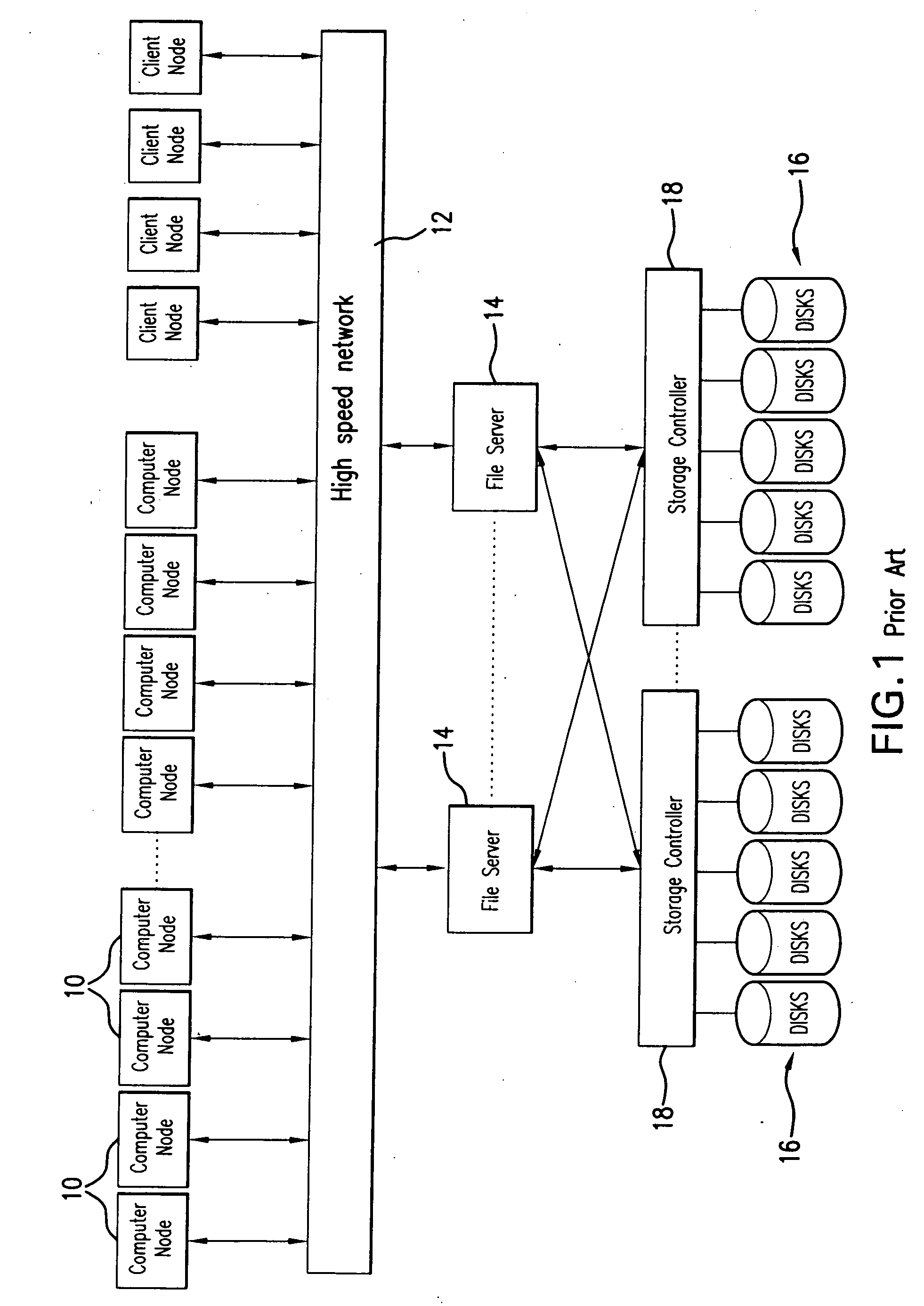
Disk drives do not perform well in satisfying random requests since the heads that record the data have to be moved to various sectors of the drive and this movement takes a great deal of time compared to the actual write or read operation.

Method used


Image

  • System and method for data migration between computer cluster architecture and data storage devices
  • System and method for data migration between computer cluster architecture and data storage devices
  • System and method for data migration between computer cluster architecture and data storage devices

Examples


Embodiment Construction

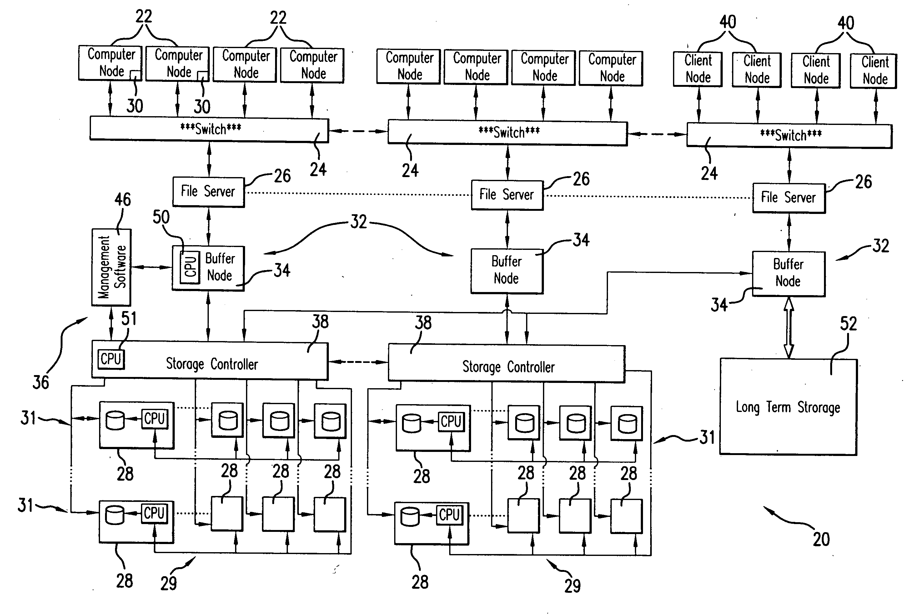
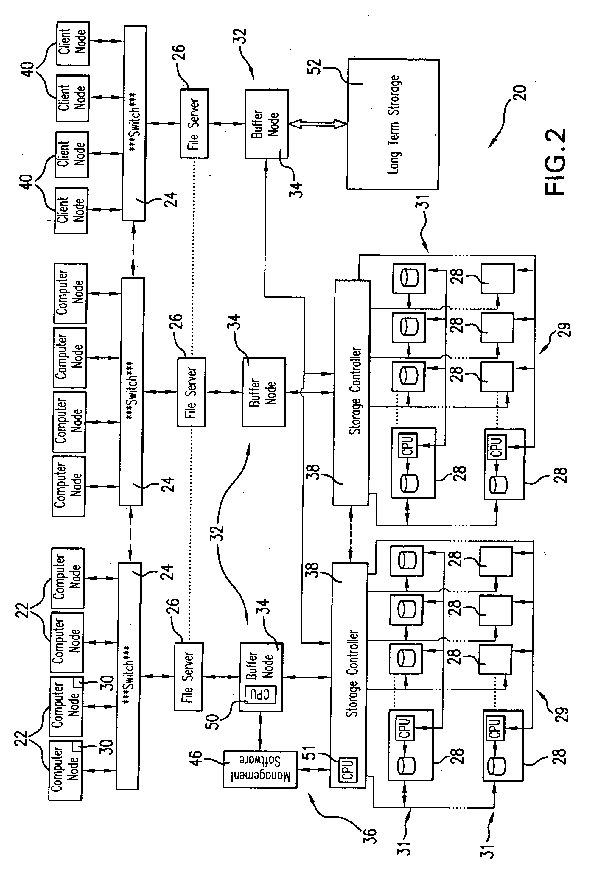
[0057]Referring to FIG. 2, the system 20 of the present invention includes compute clusters of a plurality of computer nodes 22, also referred to herein as data generating devices. The computer nodes 22 represent any data handling entity attachable to the system 20. The function of the computer nodes depends on the system application. The computer nodes may function as servers, super computing clusters, etc., and have the capacity to “write” by outputting data, as well as “read” from an external memory or any other device.

[0058]The computer nodes 22 are interconnected by a high speed network, for example including switches 24, by means of which respective computer nodes are operatively connected to the system 20 either to output data thereto or to read data therefrom. Data migration from and to the computer nodes 22 may be managed by file servers 26 to which the cache of the computer nodes 22 may be written in the I / O cycle of the computer node and which may place the data in a file...


PUM


Abstract

An improved duty cycle, increased effective bandwidth, and minimized power consumption are attained in a system for data migration between a compute cluster and disk drives by inclusion of a buffer node coupled to the compute cluster to store data received therefrom in a random fashion. The buffer node signals the computer nodes to promptly return from the I / O cycle to the computing state to improve the duty cycle of the device. The system further includes a storage controller which is coupled between the buffer node and the disk drives to schedule data transfer activity between them in an optimal orderly manner. The data transfers are actuated in the sequence determined based on minimization of seeking time and tier usage, and harvest priority, when the buffer node either reaches a predetermined storage space minimal level or a predetermined time has elapsed since the previous I / O cycle. The storage controller deactivates the disk drives which are not needed for the data transfer. Since the writing on the disk drives is conducted in the orderly manner, the system avoids the usage of excessive number of disk drives.

Description

FIELD OF THE INVENTION[0001]The present invention is directed to data migration between high performance computer cluster architectures and storage devices.[0002]More in particular, the present invention is directed to a system for data migration between high performance computer clusters and disk drives in which the data writing on the disk drive(s) is independent of the data transfer from the computer cluster that is accomplished by providing an intermediate data storage layer coupled to the computer cluster which is capable of high speed random access data storage from the computer clusters while the disk drives may “pull” the data stored on the intermediate data storage layer in an optimal organized fashion thereby attaining a highly efficient use of the disk drives, minimized “seek” time, and bandwidth advantages. When data is stored in the intermediate data storage layer, the computer cluster is immediately ordered to return from the I / O state thereof (when the data transfer t...

Claims


Application Information

Patent Timeline
Patent Type & Authority Applications(United States)
IPC IPC(8): G06F12/08
CPCG06F3/0611G06F3/0625G06F3/0656G06F3/067G06F12/0868Y02B60/1246G06F2212/2228G06F2212/284G06F2212/463Y02B60/1225G06F2212/222Y02D10/00
Inventor FELLINGER, DAVID F.PISZCZEK, MICHAEL J.COLE, JR., CHARLES DWAIN
Owner DATADIRECT NETWORKS
Learn More