Geared differential speed counter-rotatable low pressure turbine

a low pressure turbine and differential speed technology, applied in the direction of liquid fuel engines, marine propulsion, vessel construction, etc., can solve the problems of large exit area of single-stage counter-rotatable low pressure turbines, large radius low pressure turbine sections, and high undesirable effects

Active Publication Date: 2010-06-24
GENERAL ELECTRIC CO
View PDF11 Cites 117 Cited by
  • Summary
  • Abstract
  • Description
  • Claims
  • Application Information

AI Technical Summary

Benefits of technology

[0008]A gas turbine engine counter-rotatable low pressure turbine includes counter-rotatable annular outer and inner drum rotors. The outer drum rotor is rotatably connected to a low pressure shaft which is the sole shaft operable for transmitting torque and power out of the low pressure turbine. A plurality of axially spaced apart low pressure outer drum turbine blade rows extend radially inwardly from an outer shell of the outer drum rotor and a plurality of axially spaced apart low pressure inner drum turbine blade rows extend radially outwardly from the annular low pressure inner drum rotor. The low pressure outer drum turbine blade rows are interdigitated with the low pressure inner drum turbine blade rows. The outer and inner drum rotors are geared together through an epicyclic gearbox for transmitting all the torque and power produced by the inner drum rotor to the low pressure shaft. All the torque and power produced by the outer drum rotor is directly transmitted to the low pressure shaft.
[0009]An exemplary embodiment of the low pressure turbine includes the a differential thrust bearing operably disposed between the outer and inner drum rotors. The gearbox is located aft of the outer and inner drum rotors. The gearbox having planetary gears rotatably mounted on pins supported by the turbine rear frame. The gearbox includes a sun gear meshed with and rotatably mounted radially inwardly of the planetary gears, a ring gear meshed with and rotatably mounted radially outwardly of the planetary gears, the outer drum rotor connected to the ring gear, and the inner drum rotor connected to the sun gear. A radially outer roller bearing is disposed between the inner drum rotor and the turbine rear frame and a radially inner differential roller bearing disposed between outer and inner drum rotors. The pins are cantilevered off an annular carrier supported by the turbine rear frame.
[0010]An aircraft gas turbine engine having a single stage fan section with a single fan stage having a single fan blade row may incorporate the counter-rotatable low pressure turbine for drivingly the single fan stage through the low pressure shaft.

Problems solved by technology

However, among the drawbacks of this design are the large exit areas of the single stage counter-rotatable low pressure turbines.
The large exit areas of the single stage counter-rotatable low pressure turbines also requires large radius low pressure turbine sections which are also highly undesirable.

Method used


Image

  • Geared differential speed counter-rotatable low pressure turbine
  • Geared differential speed counter-rotatable low pressure turbine
  • Geared differential speed counter-rotatable low pressure turbine

Examples


Embodiment Construction

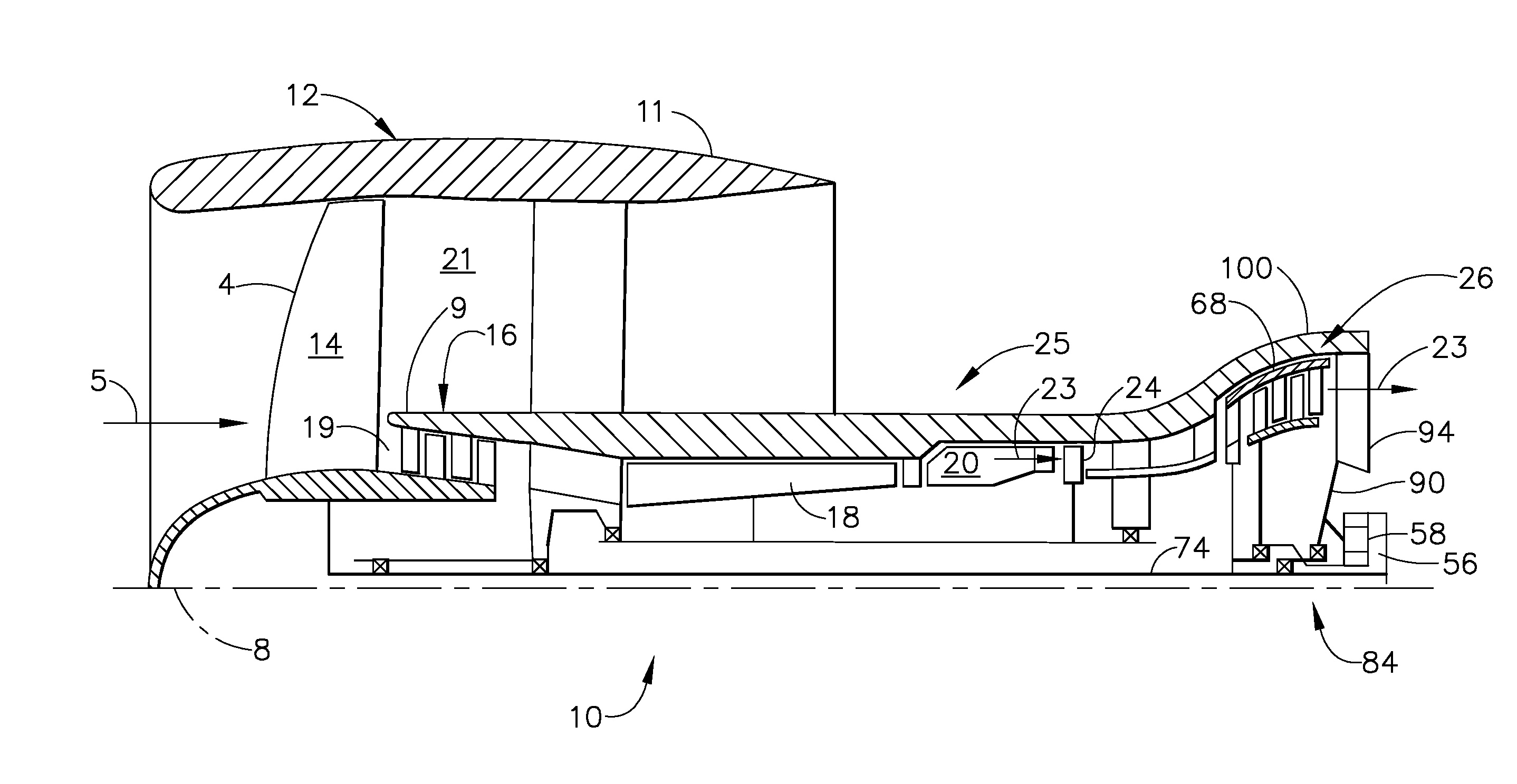
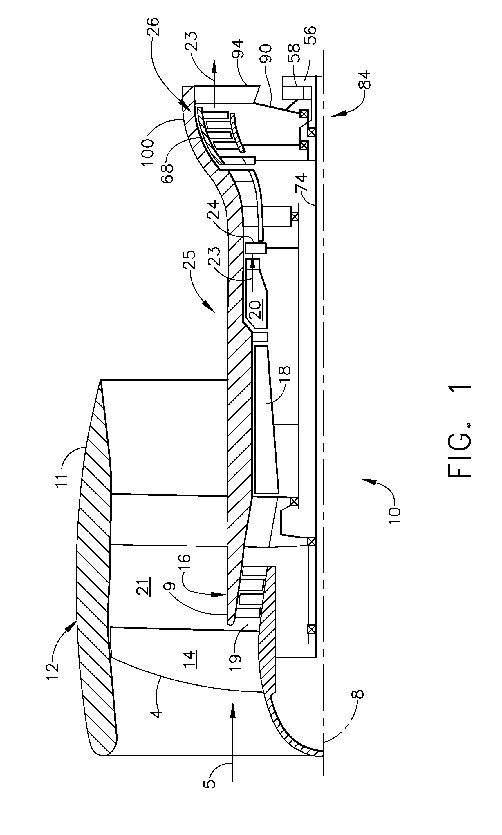
[0015]Illustrated in FIG. 1 is an exemplary turbofan gas turbine engine 10 circumscribed about an engine centerline 8 and having a single stage fan section 12 which receives inlet airflow of ambient air 5. The fan section 12 has a single fan stage 4 including a single fan blade row 14. A booster 16 is downstream of the fan stage 4. A bypass duct 21 radially bounded by a fan casing 11 and an annular radially inner bypass duct wall 9 surrounds the booster 16 and a core engine inlet duct 19 to a core engine 25. The core engine 25 includes in downstream serial flow relationship the high pressure compressor (HPC) 18, a combustor 20 which mixes fuel with the air 5 pressurized by the HPC 18 for generating combustion gases 23 which flow downstream through a high pressure turbine (HPT) 24. A counter-rotatable low pressure turbine (LPT) 26 receives the combustion gases 23 for powering the single fan stage 4 of the fan section 12 and then the spent combustion gases 23 are discharged from the e...


PUM


Abstract

A counter-rotatable low pressure turbine includes counter-rotatable outer and inner drum rotors. The outer drum rotor is connected to a sole shaft for transmitting torque and power out of the low pressure turbine. Low pressure outer drum turbine blade rows extend radially inwardly from an outer shell of the outer drum rotor. Low pressure inner drum turbine blade rows extend radially outwardly from the low pressure inner drum rotor. The outer drum turbine blade rows are interdigitated with the inner drum turbine blade rows. The drum rotors are geared together through an epicyclic gearbox for transmitting all the torque and power produced by the drum rotors to the shaft. The gearbox may be located aft of the drum rotors. A differential thrust bearing is disposed between the drum rotors. A single stage fan section of an engine is connected to the turbine by the shaft.

Description

BACKGROUND OF THE INVENTION[0001]1. Field of the Invention[0002]The invention relates to aircraft gas turbine engines with counter-rotatable low pressure turbines and, particularly, for such engines having geared together counter-rotatable low pressure turbines.[0003]2. Description of Related Art[0004]Conventional gas turbine engines of the turbofan type generally include a forward fan and booster compressor, a middle core engine, and an aft low pressure power turbine. The core engine includes a high pressure compressor, a combustor, and a high pressure turbine in a serial flow relationship. The high pressure compressor and high pressure turbine of the core engine are interconnected by a high pressure shaft. The high pressure compressor, turbine, and shaft essentially form the high pressure rotor. The high pressure compressor is rotatably driven to compress air entering the core engine to a relatively high pressure. This high pressure air is then mixed with fuel in the combustor and...

Claims


Application Information

Patent Timeline
Patent Type & Authority Applications(United States)
IPC IPC(8): F02K3/00
CPCF02C3/107Y02T50/671F02K3/072F01D5/03F01D5/06F02C3/067F05D2260/40311Y02T50/60
Inventor SCHILLING, JAN CHRISTOPHER
Owner GENERAL ELECTRIC CO
Why Eureka
Try Eureka