Method and production line for laminate assembly

a production line and laminate technology, applied in the manufacture of stator/rotor bodies, magnetic bodies, instruments, etc., can solve the problems of uneven lamination height of laminated iron cores, uneven thickness of plate thicknesses within tolerances, uneven lamination height of respective iron cores, etc., to achieve the effect of improving the yield of products

Active Publication Date: 2010-06-24
YAMADA DOBBY
View PDF4 Cites 16 Cited by
  • Summary
  • Abstract
  • Description
  • Claims
  • Application Information

AI Technical Summary

Benefits of technology

[0029]According to the invention, the controlling means is able to adjust the lamination height very minutely and accurately, accommodate the u

Problems solved by technology

However, although the laminated iron core described in the patent publication mentioned above prevents the lamination height thereof from becoming high by eliminating the gaps between respective iron core pieces which are laminated, there exists unevenness in plate thickness within the tolerance (an error in plate thickness within the dimensional tolerance) in the respective iron core pieces.
Therefore, the unevenness in the plate thickness existing in the respective iron core pieces greatly influences the lamination height of the laminated iron cores which are stacked up, wherein when the laminated iron core is produced by laminating by the set number of thin plates, unevenness is brought about

Method used


Image

  • Method and production line for laminate assembly
  • Method and production line for laminate assembly
  • Method and production line for laminate assembly

Examples


Embodiment Construction

[0039]Hereinafter, a description is given of the present invention based on the embodiment shown in the drawings. Also, the present invention is not limited to the embodiment. All modifications and variations in the matters of Claims or matters equivalent to the matters therein are considered to be included in the scope of Claims.

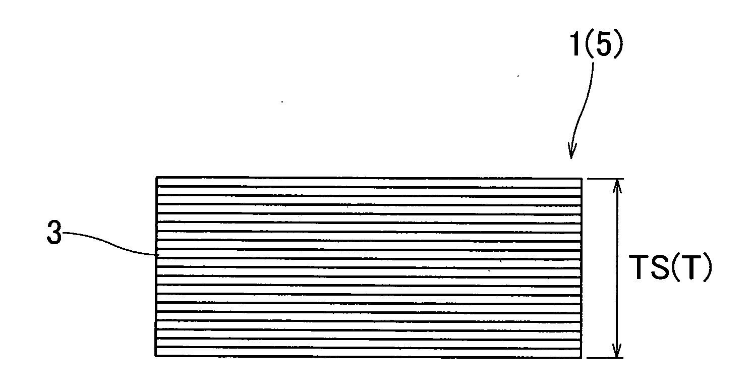
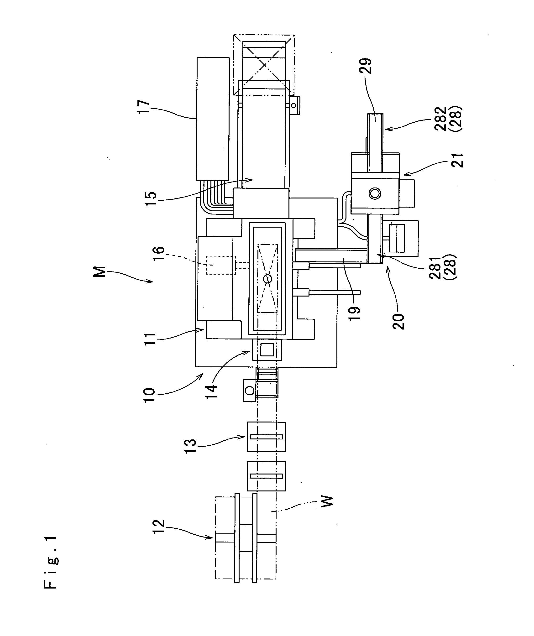
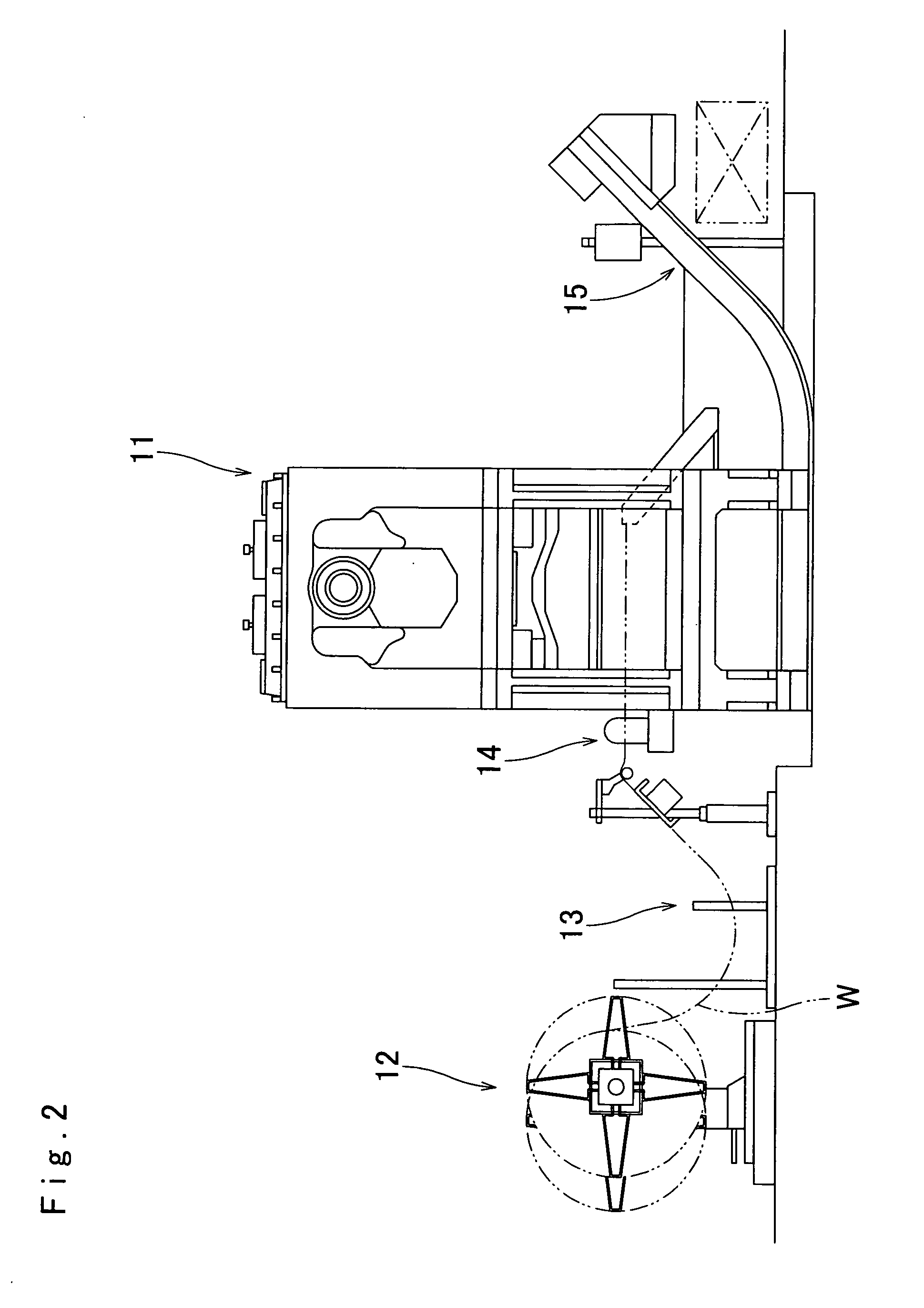
[0040]The production line M shown in FIG. 1 is a system for producing a laminate assembly 1 being, for example, a motor core. A band-shaped steel plate W being a thin plate material is wound around an uncoiler 12. The thin steel plate W led therefrom is caused to enter a press-working apparatus 10. The thin steel plate W is punched out by a press 11 of the press-working apparatus 10 to become lamination steel plates 3 of a predetermined shape. The respective lamination steel plates 3 are laminated one by one on an elevation base fitted in a recessed portion of a lower die of the press 11 and are subjected to temporary caulking. A predetermined number of lam...


PUM

PropertyMeasurementUnit
Forceaaaaaaaaaa
Pressureaaaaaaaaaa
Dimensionaaaaaaaaaa

Abstract

The production line according to the present invention is provided with a pressurization measurement apparatus adjacent to a press-working apparatus, a temporary laminate assembly worked and laminated by a press in the press-working apparatus is sent to the pressurization measurement apparatus, and a laminate assembly is produced by being pressurized and being subjected to regular caulking by a hydraulic servo press of the pressurization measurement apparatus. At this time, the lamination height of a regularly caulked laminate assembly is measured by a linear scale secured at the pressurization measurement apparatus. The main controller of a control apparatus inputs data of the measured lamination height, and adds and subtracts the set number of thin plates to be laminated of a laminate assembly by controlling the laminating means of the press-working apparatus so that the measurement lamination height is matched to the set lamination height using the measured lamination height, the preset lamination height, the height dimension tolerance, and the tolerance for judging the number of thin plates.

Description

BACKGROUND OF THE INVENTION[0001]1. Field of the Invention[0002]The present invention relates to a method and a production line for a laminate assembly formed by laminating thin plates, and in further detail, to a method and a production line for a laminate assembly having high accuracy in height by reflecting measurement data in the number of thin plates to be laminated of a newly laminated laminate assembly while measuring the lamination height of the laminate assembly press-worked and laminated.[0003]2. Description of Related Art[0004]For example, a motor core produced as an electric component is formed as a laminate assembly by punching out thin steel plates to a predetermined shape by press-working, laminating and caulking the same. A method has been known by Japanese Patent Publication No. 2720138, by which a laminated iron core used as a motor core is produced by forming caulking parts in respective laminated steel plates, which composes a laminate assembly, by means of cutti...

Claims


Application Information

Patent Timeline
IPC IPC(8): B29C65/48B29C43/58
CPCB32B37/1054B32B41/00B32B2311/00B32B2457/00Y10T29/49004Y10T29/5317Y10T29/4902Y10T29/49075H02K15/02
Inventor SHIRAI, KUNIYASUHIRAMITSU, KAZUOISHIHARA, SOTARO
Owner YAMADA DOBBY
Why Eureka
Try Eureka