Package structure and method for a piezoelectric transformer

a piezoelectric transformer and packaging technology, applied in piezoelectric/electrostrictive/magnetostrictive devices, piezoelectric/electrostriction/magnetostriction machines, electrical equipment, etc., can solve the problems of reducing affecting the efficiency of the piezoelectric transformer, so as to reduce the heat generation, reduce the contact resistance, and conduct the pi

Inactive Publication Date: 2010-06-24
NEWLIGHTING ELECTRONICS
View PDF3 Cites 2 Cited by
  • Summary
  • Abstract
  • Description
  • Claims
  • Application Information

AI Technical Summary

Benefits of technology

[0009]As can be seen from the above, in the disclosure, the shell supporting the piezoelectric transformer at its node plane allows the piezoelectric transformer to vibrate freely, connection points with the electrode of the piezoelectric transformer decrease contact resistance, thus decrease the heat generation, and the electrical connection frames and connection points also conduct heat from the piezoelectric transformer effectively. So a piezoelectric transformer with the above package structure and method has high efficiency. Moreover, the present invention provides an easy interface with the outside circuit though the connection pins.

Problems solved by technology

Because of the principle of the piezoelectric transformer, the free vibration must be supported and impediment to the vibration will decrease the efficiency of the piezoelectric transformer extremely.
Although the piezoelectric transformer has high efficiency, dissipation of the heat is also needed.
Heat generation and temperature rise of the piezoelectric transformer will decrease the efficiency of the piezoelectric transformer and involve into a vicious circle.

Method used


Image

  • Package structure and method for a piezoelectric transformer
  • Package structure and method for a piezoelectric transformer
  • Package structure and method for a piezoelectric transformer

Examples


Embodiment Construction

[0017]The following description is merely exemplary in nature and is not intended to limit the present disclosure, application, or uses.

[0018]The embodiments are further illustrated in detail in conjunction with the drawings to make embodiments of the technical solutions and the advantages more apparent.

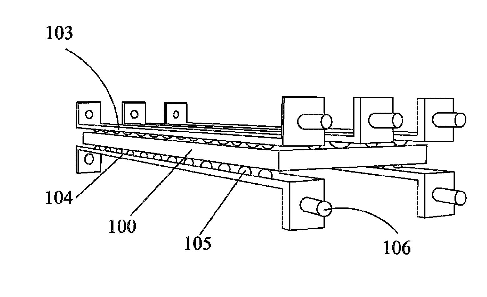
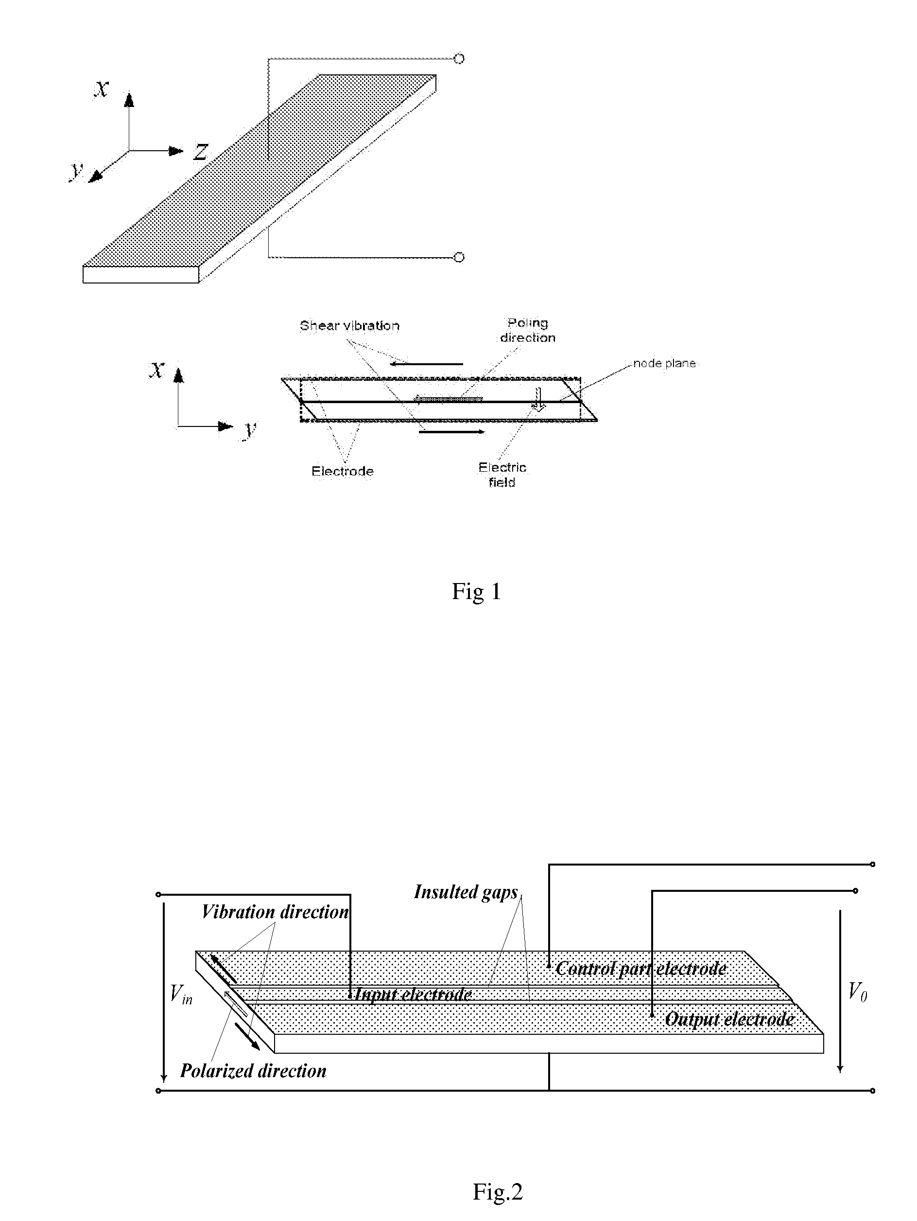
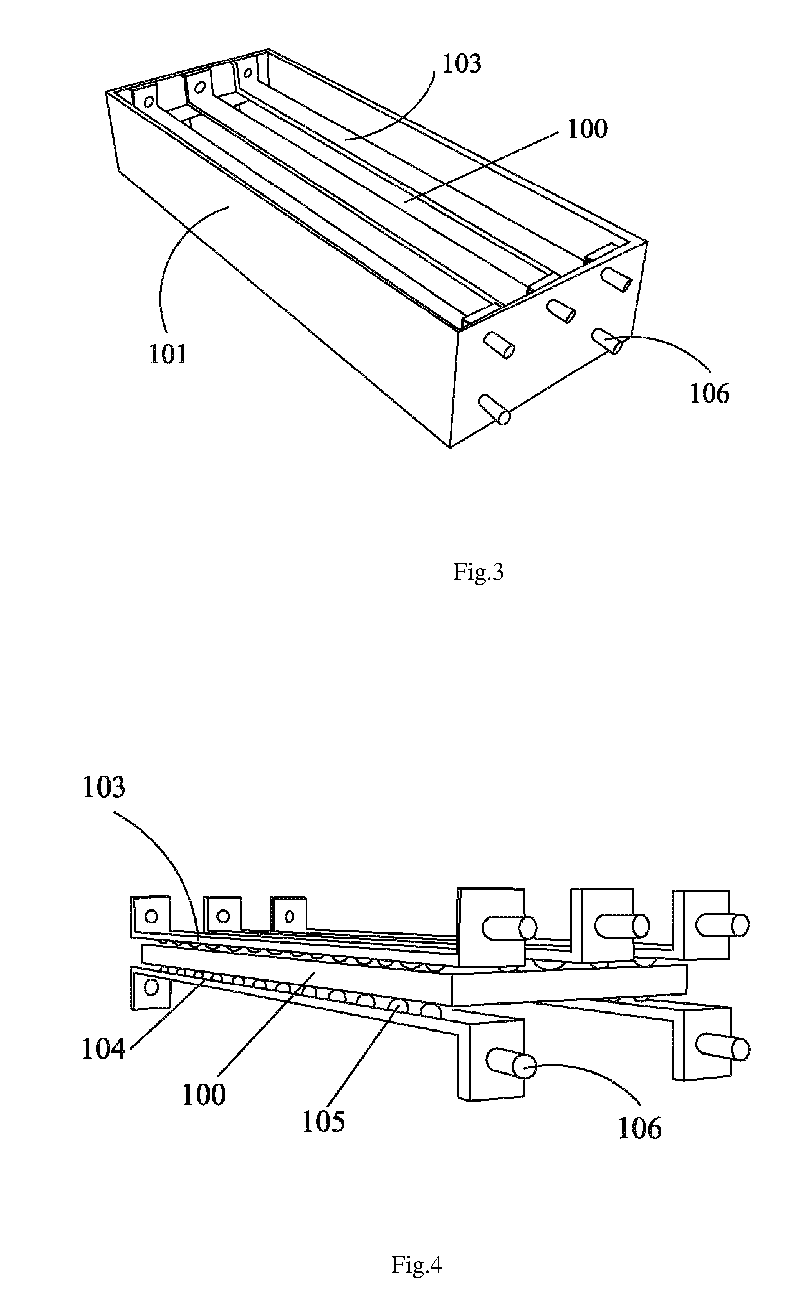
[0019]As shown in FIG. 3, FIG. 4 and FIG. 6, the outside shell 101 fixes the piezoelectric transformer (PT) 100 at its node plane, electrical connection frames 103, 104 connect with the electrodes of the piezoelectric transformer 100 and conduct thermal energy from the piezoelectric transformer 100, connection pins 106 are deposited on the electrical connection frames 103,104 for connecting to the outside circuit. As shown in FIG. 1, the node plane is on the middle of the X axis for the shear vibration mode piezoelectric transformer. The frames 103,104 fix on the shell and connect with the electrodes of piezoelectric transformer by connection points 105, as shown in the FIG. 4 and FI...


PUM


Abstract

The disclosed is package structure for a piezoelectric transformer, which comprises: a shell for supporting the piezoelectric transformer at its node plane; a plurality of electrical connection frames which are fixed on the shell for connecting with electrodes of the piezoelectric transformer and conducting heat from piezoelectric transformer by connection points arranging along the electrical connection frame; and a plurality of connection pins deposited on the electrical connection frames for connecting to the outside circuit. Further, the shell has a wedge structure part which fixes the piezoelectric transformer at its node plane. Correspondingly, a package method for a piezoelectric transformer is also disclosed. Thus, the structure and package method allow a piezoelectric transformer to vibrate freely and have good heat management.

Description

TECHNICAL FIELD OF THE INVENTION[0001]The present invention generally relates to the field of the piezoelectric transformer, and more particularly to package structure and method for a piezoelectric transformer.BACKGROUND OF THE INVENTION[0002]A piezoelectric transformer (PT) converts electric energy into ultrasonic vibration by converse piezoelectric effect at the input part, and the ultrasonic vibration into electric energy with a different voltage by piezoelectric effect at the output part. Compared with a conventional Electromagnetic transformer, a piezoelectric transformer has many advantages such as high-power density, high efficiency, low profile, small size, light weight, no windings, electromagnetic noise-free operation, and no inflammability. More, the shear mode piezoelectric transformer is potential piezoelectric transformer that the power density and output power are superior to other piezoelectric transformer for its large K15 (electromechanical coupling coefficient) a...

Claims


Application Information

Patent Timeline
Patent Type & Authority Applications(United States)
IPC IPC(8): H01L41/053
CPCH01L41/107H01L41/053H10N30/88H10N30/40
Inventor DU, JINLONGWU, BIN
Owner NEWLIGHTING ELECTRONICS
Why Eureka
Try Eureka