
Object tracking system, method and smart node using active camera handoff

a distributed object and object technology, applied in the field of intelligent distributed object tracking system, can solve the problems of system performance substantially reduced, system cannot automatically track this object, and cannot reach real-time tracking

Inactive Publication Date: 2010-06-24
IND TECH RES INST
View PDF19 Cites 149 Cited by
  • Summary
  • Abstract
  • Description
  • Claims
  • Application Information

AI Technical Summary

Benefits of technology

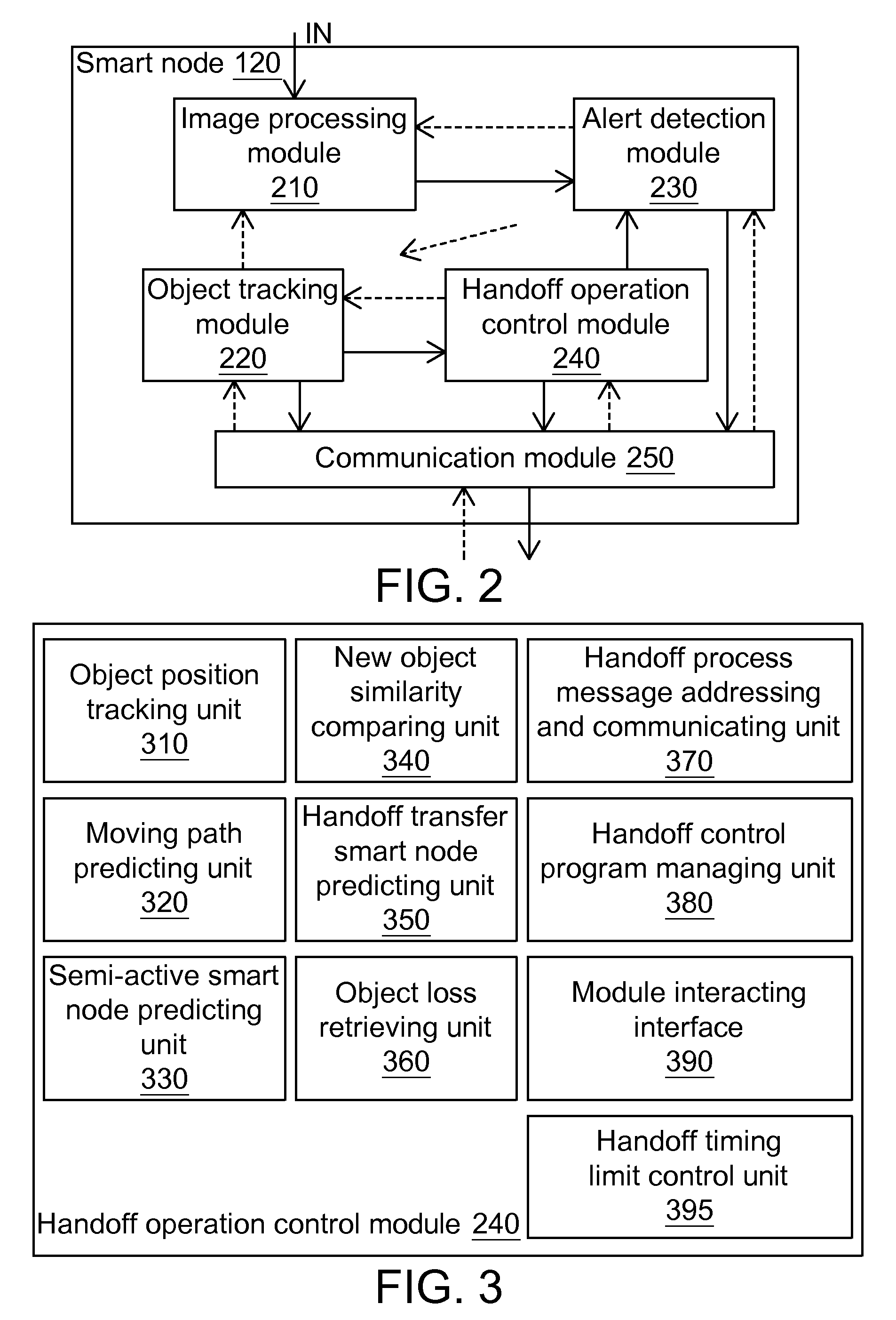
The patent describes an intelligent distributed object tracking system that uses cameras and smart nodes to track objects. The system detects the position of an object and predicts its future movement based on metadata from the cameras. The smart nodes communicate with a control center and can make handoff transfers to other smart nodes when necessary. The system can also detect and track alerts and alert levels, and enable a dedicated handoff control program for the object. The technical effects of the system include improved object tracking and better security control.

Problems solved by technology

However, when the object left the camera FOV and enters into the new FOV of another camera, the system will not be able to automatically track this object, or the system will be treated this object as a new object to continue tracking.
However, as for the centralized vision-based object tracking system, it is not possible to reach a real-time tracking.
In addition, when the number of tracked objects is increased, or the number of cameras in the system is increased, the system performance will be substantially reduced.
This problem usually occurs in when the object across the camera FOV.
However, such systems are not practical because of the need for additional sensors.
However, the system cannot dynamically control whether or not only the objectives of specific to perform the alert detection, although it can obtain data of the specific object by querying the event database later.

Method used


Image

  • Object tracking system, method and smart node using active camera handoff
  • Object tracking system, method and smart node using active camera handoff
  • Object tracking system, method and smart node using active camera handoff

Examples


Embodiment Construction

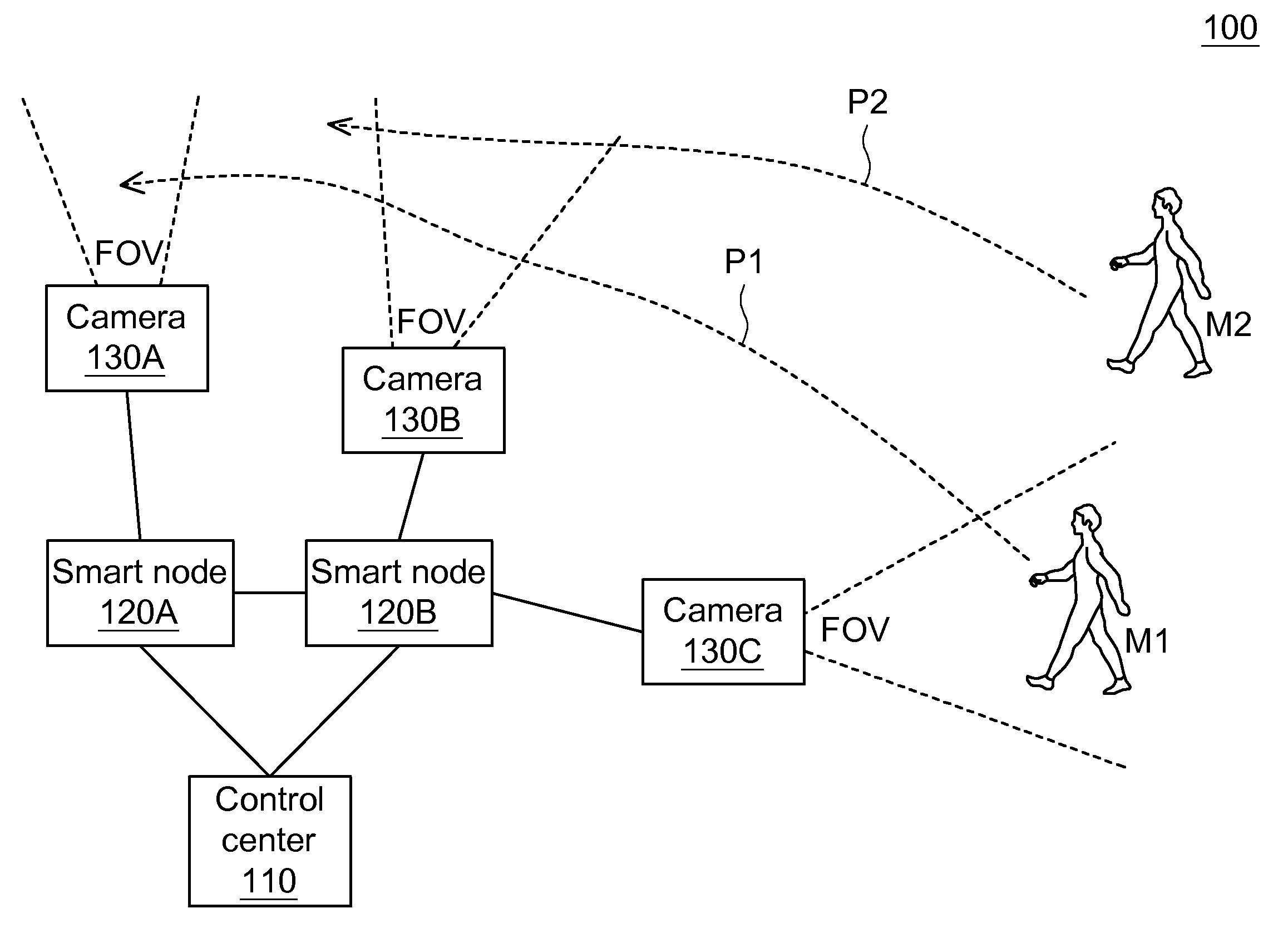
[0023]An intelligent distributed object tracking system according to exemplary embodiment of the invention uses camera handoff mechanism and can simultaneously and continuously track multiple objects even if the FOVs of cameras are not overlapped.

[0024]In the intelligent distributed object tracking system according to the embodiment of the invention, during handoff transfer operation, smart nodes transmit monitor metadata to each other so that the next smart node in charge of tracking knows which objects are alert subjects in advance and the control of event detection and alert can be achieved.

[0025]In the intelligent distributed object tracking system according to the embodiment of the invention, during object tracking, no matter what selects for a while, there is a smart node responsible for tracking, in order to enhance the usefulness of tracking.

[0026]FIG. 1 is a schematic illustration showing an intelligent distributed object tracking system 100 according to an embodiment of th...


PUM


Abstract

If an active smart node detects that an object leaves a center region of a FOV for a boundary region, the active smart node predicts a possible path of the object. When the object gets out of the FOV, the active smart node predicts the object appears in a FOV of another smart node according to the possible path and a spatial relation between cameras. The active smart node notifies another smart node to become a semi-active smart node which determines an image characteristic similarity between the object and a new object and returns to the active smart node if a condition is satisfied. The active smart node compares the returned characteristic similarity, an object discovery time at the semi-active smart node, and a distance between the active smart node and the semi-active smart node to calculate possibility.

Description

[0001]This application claims the benefit of Taiwan application Serial No. 97149522, filed Dec. 18, 2008, the subject matter of which is incorporated herein by reference.TECHNICAL FIELD[0002]The application relates in general to an intelligent distributed object tracking system, and more particularly to an intelligent distributed object tracking system using a handoff mechanism to achieve continuous real-time tracking on at least one object.BACKGROUND[0003]Video surveillance systems have been widely used in various occasions, such as bank surveillance and public surveillance. The video surveillance system can momentarily track an object, such as a character or a vehicle, and thus play a very important role in the vision-based object tracking.[0004]At present, the vision-based object tracking system is broadly divided into four categories. In the first category of vision-based object tracking system, the camera will continuously track the object in a field of view (FOV). However, whe...

Claims


Application Information

Patent Timeline
Patent Type & Authority Applications(United States)
IPC IPC(8): H04N5/225
CPCG06K9/00771G06T7/2093H04N5/247G06T2207/30232G08B13/19645G06T2207/30196G06T7/292G06V20/52H04N23/90
Inventor CHENG, SUNG-PINGJANG, LIH-GUONGKUO, JEN-YAUCHUANG, JEN-HUI
Owner IND TECH RES INST
Learn More