Dynamic autofocus method and system for assay imager

an assay imager and autofocus technology, applied in the field of sample imaging, can solve the problems of inability to capture images, increasing the number of parts that may fail, increasing the cost, complexity, etc., and increasing the cos

Inactive Publication Date: 2010-06-24
ILLUMINA INC
View PDF15 Cites 218 Cited by
  • Summary
  • Abstract
  • Description
  • Claims
  • Application Information

AI Technical Summary

Problems solved by technology

However, conventional optical imagers have experienced certain limitations.
However, conventional focus mechanisms utilize components separate and part from the optical components that are used to capture images of the region of interest, thereby increasing the cost, complexity, and number of parts that may potentially fail.
Further, in certain optical systems, the image cannot be captured until after the focus mechanism first performs focus measurements and adjusts the optical components relative to the area of interest.
Thus, the focus mechanism may adjust the focal plane in a manner that is incomplete or inaccurate.

Method used


Image

  • Dynamic autofocus method and system for assay imager
  • Dynamic autofocus method and system for assay imager
  • Dynamic autofocus method and system for assay imager

Examples


Embodiment Construction

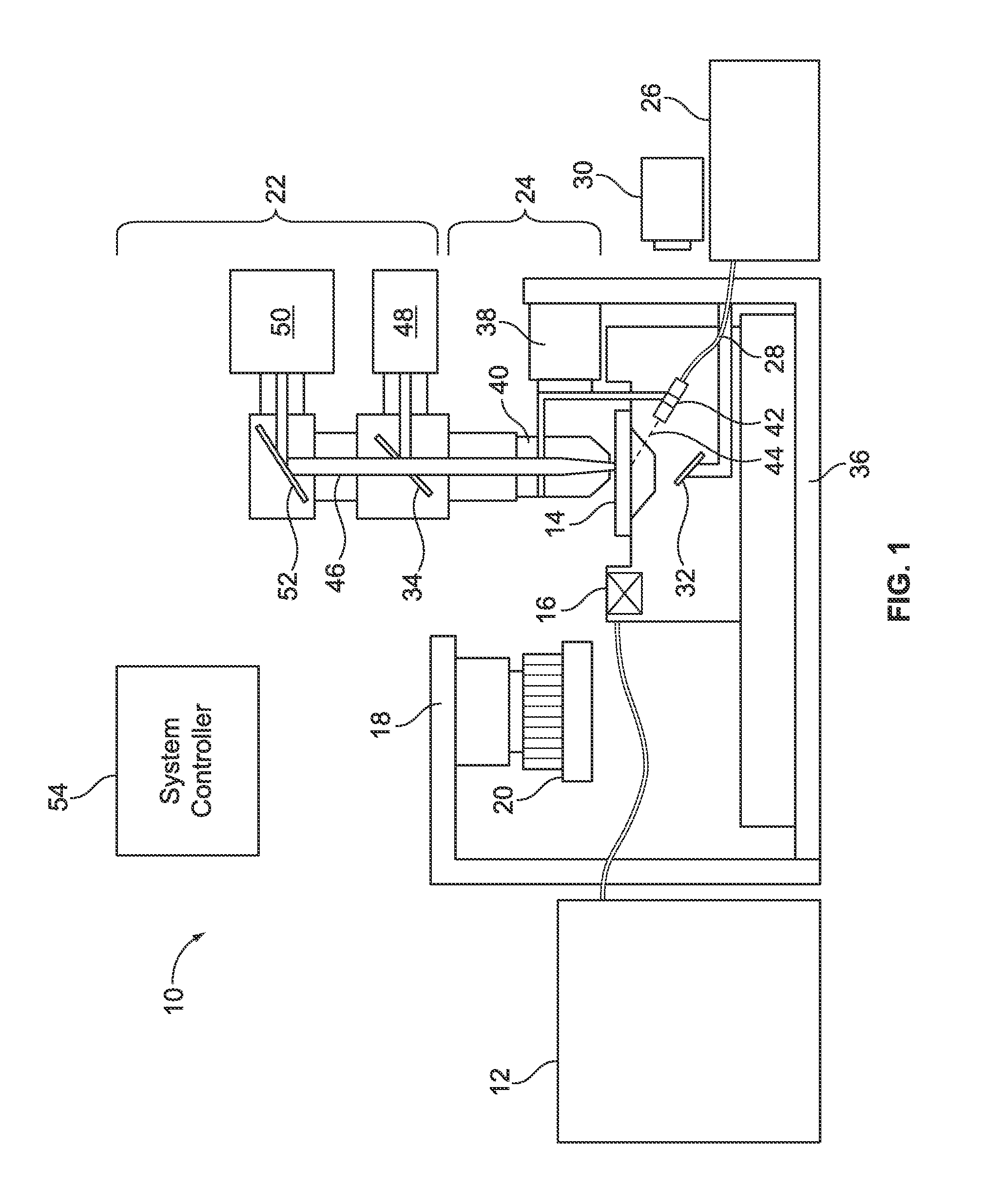
[0032]FIG. 1 illustrates an optical imaging system 10 that is formed in accordance with an embodiment. By way of example, the imaging system 10 may be constructed to include various components and assemblies as described in PCT application PCT / US07 / 07991, titled “System and Devices for Sequence by Synthesis Analysis”, filed Mar. 30, 2007 and / or to include various components and assemblies as described in PCT application PCT / US2008 / 077850, titled “Fluorescence Excitation and Detection System and Method”, filed Sep. 26, 2008, for both of which the complete subject matter are incorporated herein by reference in their entirety. In particular embodiments, the imaging system 10 can include various components and assemblies as described in U.S. Pat. No. 7,329,860, of which the complete subject matter is incorporated herein by reference in its entirety.

[0033]As can be seen in FIG. 1, a fluid delivery module 12 directs the flow of reagents (e.g., fluorescent nucleotides, buffers, enzymes, cl...


PUM

PropertyMeasurementUnit
diameteraaaaaaaaaa
z-distanceaaaaaaaaaa

Abstract

A method and system are provided for controlling focus dynamically of a sample imager. The method comprises scanning a sample with an optical assembly that apportions the sample into regions based on a scan pattern. The optical assembly has a focal setting with respect to the sample. The method further comprises shifting the focal setting of the optical assembly during scanning of the sample, and detecting one or more images representative of one of the regions from the sample. The one or more images have associated degrees of focus corresponding to the focal setting of the optical assembly. The method analyzes the image(s) to obtain a focus score or scores corresponding thereto, where the focus scores represent a degree to which the optical assembly was in focus when detecting the images. The method adjusts the focus setting based on the focus score(s).

Description

CROSS REFERENCE TO RELATED APPLICATIONS[0001]This application claims the benefit of U.S. Provisional Application No. 61 / 122,550, filed Dec. 15, 2008 and having the same title, which is hereby incorporated by reference in the entirety.BACKGROUND OF THE INVENTION[0002]Embodiments of the present invention relate generally to sample imaging, and more specifically to dynamic autofocus methods and systems for assay imaging.[0003]A wide variety of optical systems exist that capture images of an area of interest on assays for subsequent analysis. Each image may be obtained by detecting light produced across an entire area of interest on an assay substrate at one point in time. Alternatively, each image may be obtained by scanning an illumination source across the area of interest while detecting light produced at the current illuminated spot. For example, a series of successive line scans of a tightly focused illumination beam may be directed across the area of interest, such as in a raster...

Claims


Application Information

Patent Timeline
Patent Type & Authority Applications(United States)
IPC IPC(8): H04N5/225G06K9/40
CPCG01N21/6458G01B11/24H04N5/23212G02B21/244H04N23/672G01B9/02063G02B26/10G02B26/127G01N2015/1452G02B7/38H04N23/67C12Q1/6818C12Q1/6874G01N21/6428
Inventor SEGALE, DARREN R.MOON, JOHN A.REN, HONGJI
Owner ILLUMINA INC
Why Eureka
Try Eureka