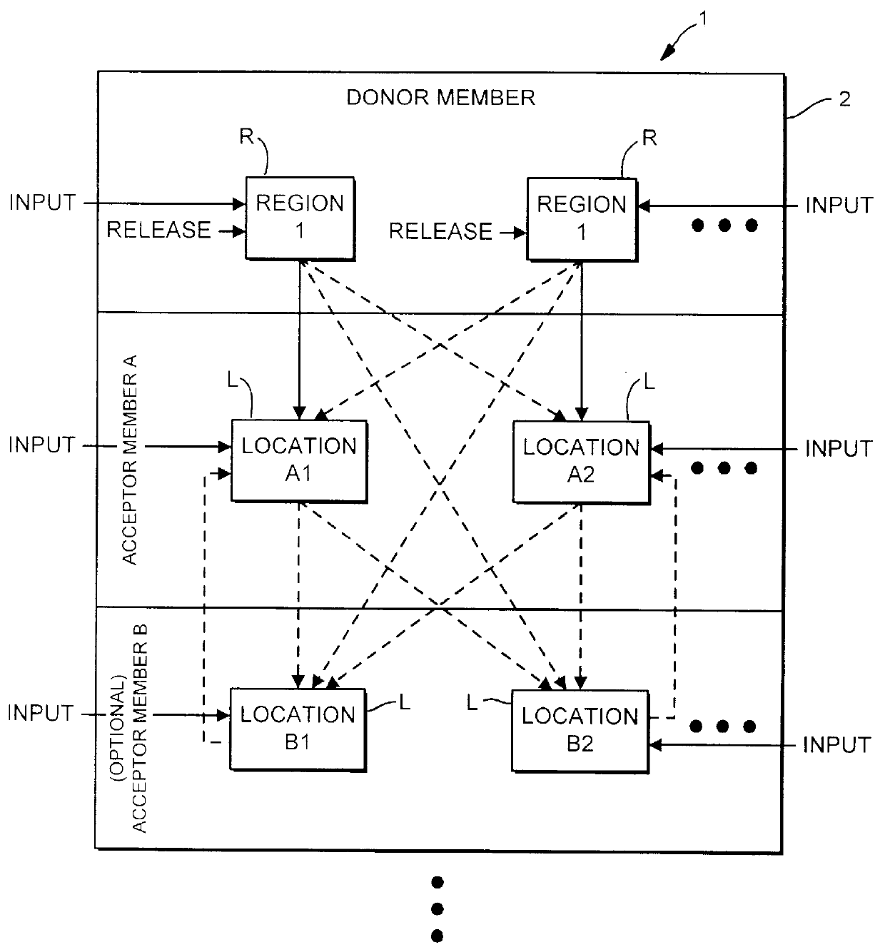
In one exemplary embodiment, the invention provides a fluid
transfer system which comprises a donor member having a plurality of separate regions. At least some of the regions contain at least one
chemical composition, with each
chemical composition being distinct or physically separated from any other
chemical composition in the donor member. An
acceptor member is also provided and includes a plurality of defined locations which are each adapted to receive a
liquid medium. A
transfer mechanism is provided to systematically transfer at least some of the chemical compositions from the donor member regions to at least some of the
acceptor member locations such that the locale of each transferred chemical composition within the
acceptor member is known. Further, each of the acceptor member locations has a volume that is less than about 500 .mu.l. In this way, a large number of acceptor member locations may be provided within a single
system to efficiently transfer, in parallel fashion, large numbers of chemical compositions from the donor member to the acceptor member where evaluation or further
processing of the chemical compositions may proceed.
In another particular aspect, the chemical compositions are included on solid supports which are held within the donor member regions so that at least some of the chemical compositions may be released into the
liquid medium prior to being transferred. Such solid supports may include, for example, beads having the chemical compositions synthesized thereon, the inner walls of wells to which photolithographic techniques have been applied to synthesize the chemicals thereon, the inner walls of wells into which a chemical has been placed to react with the walls of the wells (e.g., plastic walls), and the like. In still another aspect, the donor member, the
transfer mechanism and the acceptor member are isolated from the outside environment. In this manner,
evaporation of the chemical compositions from the
system will be greatly reduced, thereby allowing smaller volumes of liquids to be employed.
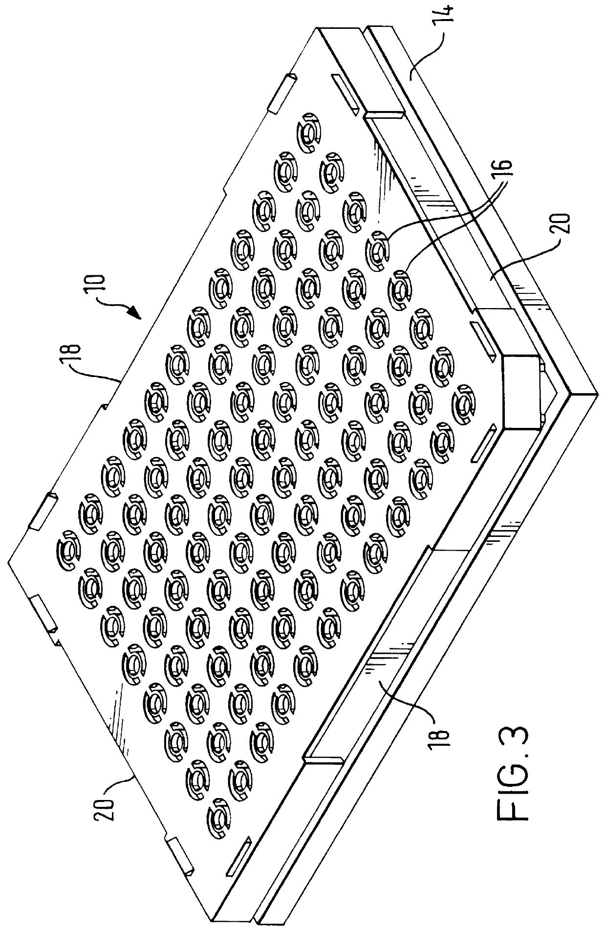
The hole may have a circular or non-circular profile. Holes having a non-circular profile are advantageous in that they are less-likely to become clogged with spherical articles, such as beads. Exemplary non-circular profiles include a triangular profile, a square profile, a slit, and a crack. Further, the holes are typically sized to exclude spheres larger than 500 .mu.m, preferably 300 .mu.m, more preferably 200 m. The holes are also typically sized to allow the passage of spherical particles less than 5 .mu.m, preferably less 10 .mu.m. In a preferred embodiment, each well includes only a
single hole. However, it will be appreciated that a small number of holes could be included in each well. The number of holes is typically less than 10, preferably less than 5.
the holding vessels. Alternatively, a vacuum source may be provided to draw the fluids through the capillary holes. In another alternative, fluids may be removed from the wells by placing an
absorbent material against each of the well bottoms. The
absorbent material will preferably be made of or be coated with a material which has a
contact angle with water of less than 90.degree., so that the fluid in the well will be drawn through the holes and into the
absorbent material. In this manner, fluids may be rapidly drained from the wells without the need for a
centrifuge or
vacuum manifold.
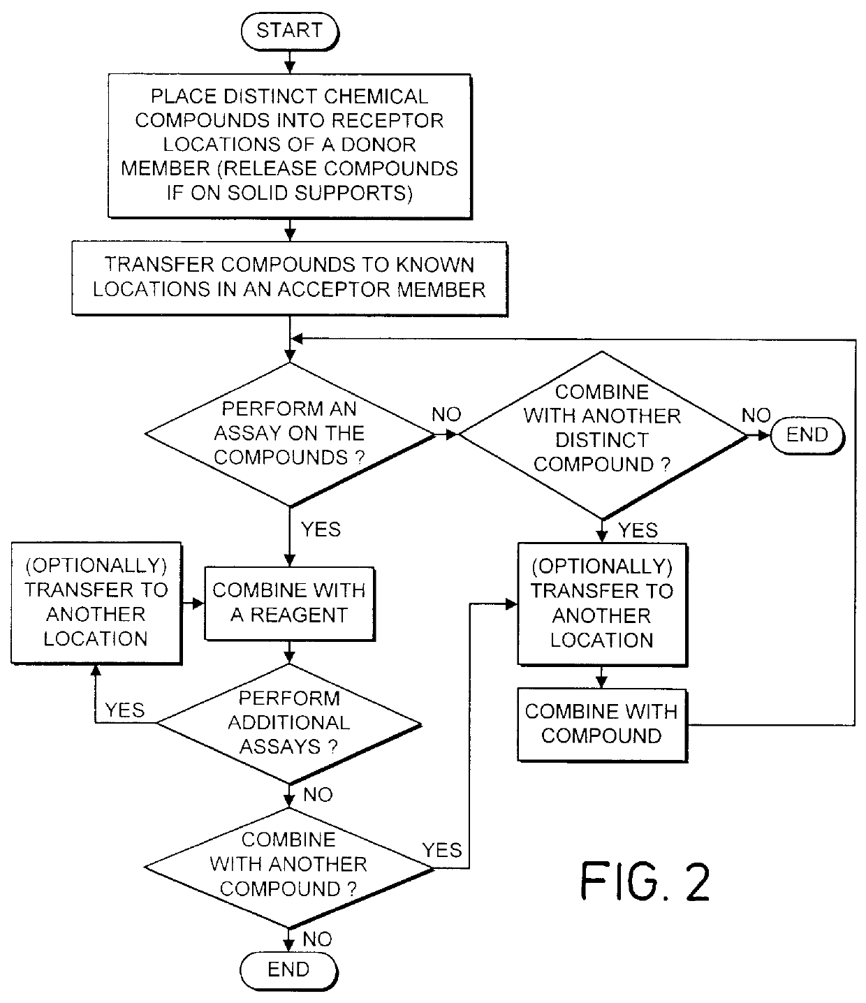
If the released compound in each well is transferred into a separate and corresponding holding vessel, substantially all of the released compound will preferably be transferred from each well. A portion of the compounds in each of the holding vessels may then be transferred into reaction vessels to form combined compounds within the reaction vessels. The assays are then performed on the combined compounds within the reaction vessels. If a positive result is produced with the
assay on the combined compound, additional assays may then be performed on the compounds remaining in the corresponding holding vessels. In this way, the time required to evaluate the compounds may be greatly reduced since, if a positive result is not produced with the
assay on the combined compound in the reaction vessel, it will not be necessary to perform individual assays on the compounds within each holding vessel. Further, if a positive result is produced in a reaction vessel, additional compounds do not need to be released from the articles since a portion of the removed compound will remain in each holding vessel and will be available for analysis.

