Apparatus for manipulation of an optical element

a technology of optical elements and apparatuses, applied in the direction of photomechanical apparatuses, instruments, printers, etc., can solve the problem of maximum stiffness in the direction of effective force, and achieve the effect of preventing the introduction of undesirable deformations

Active Publication Date: 2010-06-24
CARL ZEISS SMT GMBH
View PDF24 Cites 10 Cited by
  • Summary
  • Abstract
  • Description
  • Claims
  • Application Information

AI Technical Summary

Benefits of technology

[0010]The present invention is based on the object of providing an apparatus of the type mentioned initially, which allows precise manipulation of optical elements or assemblies in up to six degrees of freedom, with the aid of as far as possible preventing the introduction of undesirable deformations.

Problems solved by technology

This is due to the almost vanishing amount of stiffness in this degree of freedom.
However, there is maximum stiffness into the direction of the effective force, caused by the actuators of the actuator device.

Method used


Image

  • Apparatus for manipulation of an optical element
  • Apparatus for manipulation of an optical element
  • Apparatus for manipulation of an optical element

Examples


Embodiment Construction

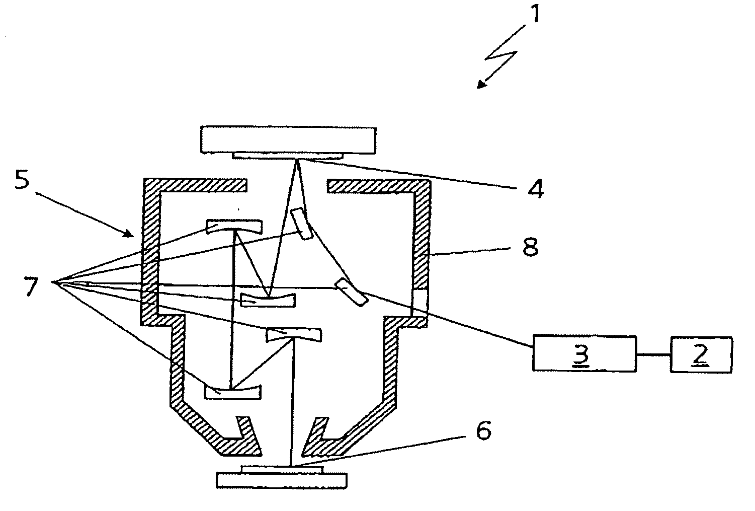
[0041]As can be seen from FIG. 1, an EUV projection illumination system 1 has a light source 2, an EUV illumination system 3 for illumination of a field on a plane 4 in which a structured mask is arranged, as well as a projection objective 5 for imaging the structured mask in the plane 4 onto a light-sensitive substrate 6. An EUV projection illumination system 1 such as this is known from EP 1 278 089 A2.

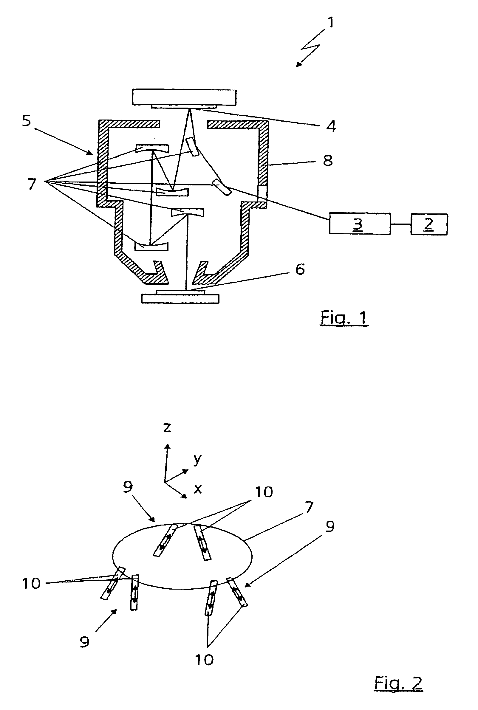
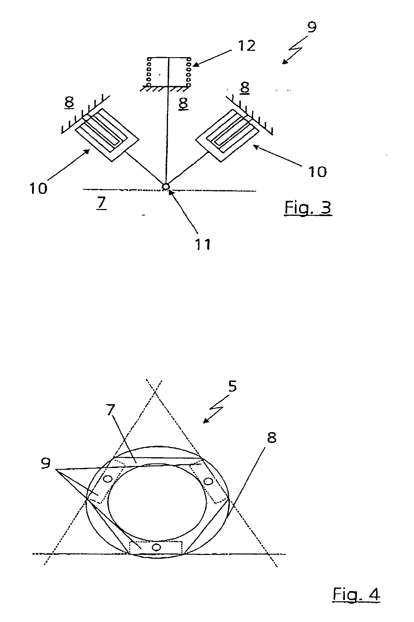
[0042]A capability is normally required in the projection objective 5 for manipulation of optical elements, such as mirrors 7 or optical assemblies (not illustrated) relative to a housing 8 of the projection objective 5. Appropriate links with actuator devices 9 for the mirrors 7 with respect to the housing 8 of the projection objective 5 are provided for this purpose, (in this context see, in particular, FIGS. 4 and 5). In another exemplary embodiment, the optical elements could also be manipulated relative to a sensor frame or relative to a measurement structure of the projection ...


PUM

PropertyMeasurementUnit
angleaaaaaaaaaa
angleaaaaaaaaaa
degrees of freedomaaaaaaaaaa

Abstract

The invention relates to an apparatus for manipulation of an optical element (7) in up to six degrees of freedom with respect to a structure (8) via at least three actuator devices (9). The actuator devices (9) each have at least two force-controlled actuators, which each produce an effective force along one degree of freedom, with linking points (11) of the actuator devices (9) acting directly on the optical element (7).

Description

FILED OF THE INVENTION[0001]The invention relates to an apparatus for manipulation of an optical element in up to six degrees of freedom with respect to a structure via at least three actuator devices. The invention likewise relates to an actuator device for direct linking of an optical element or an optical assembly. The invention also relates to an apparatus for manipulation of an optical assembly in up to six degrees of freedom with respect to a structure via at least three actuator devices. Further, the invention relates to a force-controlled actuator and a force-controlled actuator device.DESCRIPTION OF THE RELATED ART[0002]An apparatus for manipulation of an optical element in up to six degrees of freedom with respect to a structure via at least three actuator devices is known from EP 1 312 965 A1.[0003]Optical elements, in particular mirrors, are mainly manipulated in three degrees of freedom, and piezoactuators, for example, are used for this purpose.[0004]U.S. Pat. No. 5,98...

Claims


Application Information

Patent Timeline
Patent Type & Authority Applications(United States)
IPC IPC(8): G03B27/54G02B7/182G03F7/20
CPCG02B7/182G02B7/1822H02K41/035G03F7/70258G03F7/70825G02B7/183G02B7/1828
Inventor MUEHLBEYER, MICHAELLIPPERT, JOHANNES
Owner CARL ZEISS SMT GMBH
Why Eureka
Try Eureka