Method of Driving a Gate Line and Gate Drive Circuit for Performing the Method

a gate drive and gate line technology, applied in the direction of digital storage, instruments, optics, etc., can solve the problems of no known asg structure that effectively controlled noise generation, and the noise generated by the clock signal, so as to prevent the effect of voltage stress and the generation of nois

Active Publication Date: 2010-06-24
SAMSUNG DISPLAY CO LTD
View PDF16 Cites 53 Cited by
  • Summary
  • Abstract
  • Description
  • Claims
  • Application Information

AI Technical Summary

Benefits of technology

[0028]According to a method of driving a gate line and a gate drive circuit for performing the method, during a period in which a gate signal is low, a first node receives a ground voltage and an output terminal outputs the gate signal corresponding to the ground voltage, so that characteristic changes caused by voltage stress may be prevented.

Problems solved by technology

Since the ASG technology includes selectively outputting a clock signal in which a phase is continuously changing to generate a gate signal, noise is generated by the clock signal even when not driving.
However, no known ASG structure has effectively controlled noise generated when the temperature of a gate drive part becomes high due to being driven for a long time.

Method used


Image

  • Method of Driving a Gate Line and Gate Drive Circuit for Performing the Method
  • Method of Driving a Gate Line and Gate Drive Circuit for Performing the Method
  • Method of Driving a Gate Line and Gate Drive Circuit for Performing the Method

Examples


Embodiment Construction

[0039]The present invention is described more fully hereinafter with reference to the accompanying drawings, in which exemplary embodiments of the present invention are shown. The present invention may, however, be embodied in many different forms and should not be construed as limited to exemplary embodiments set forth herein. Rather, exemplary embodiments are provided so that this disclosure will be thorough and complete, and will fully convey the scope of the present invention to those skilled in the art. In the drawings, the sizes and relative sizes of layers and regions may be exaggerated for clarity.

[0040]The terminology used herein is for the purpose of describing particular example embodiments only and is not intended to be limiting of the present invention.

[0041]Hereinafter, the present invention will be explained in detail with reference to the accompanying drawings.

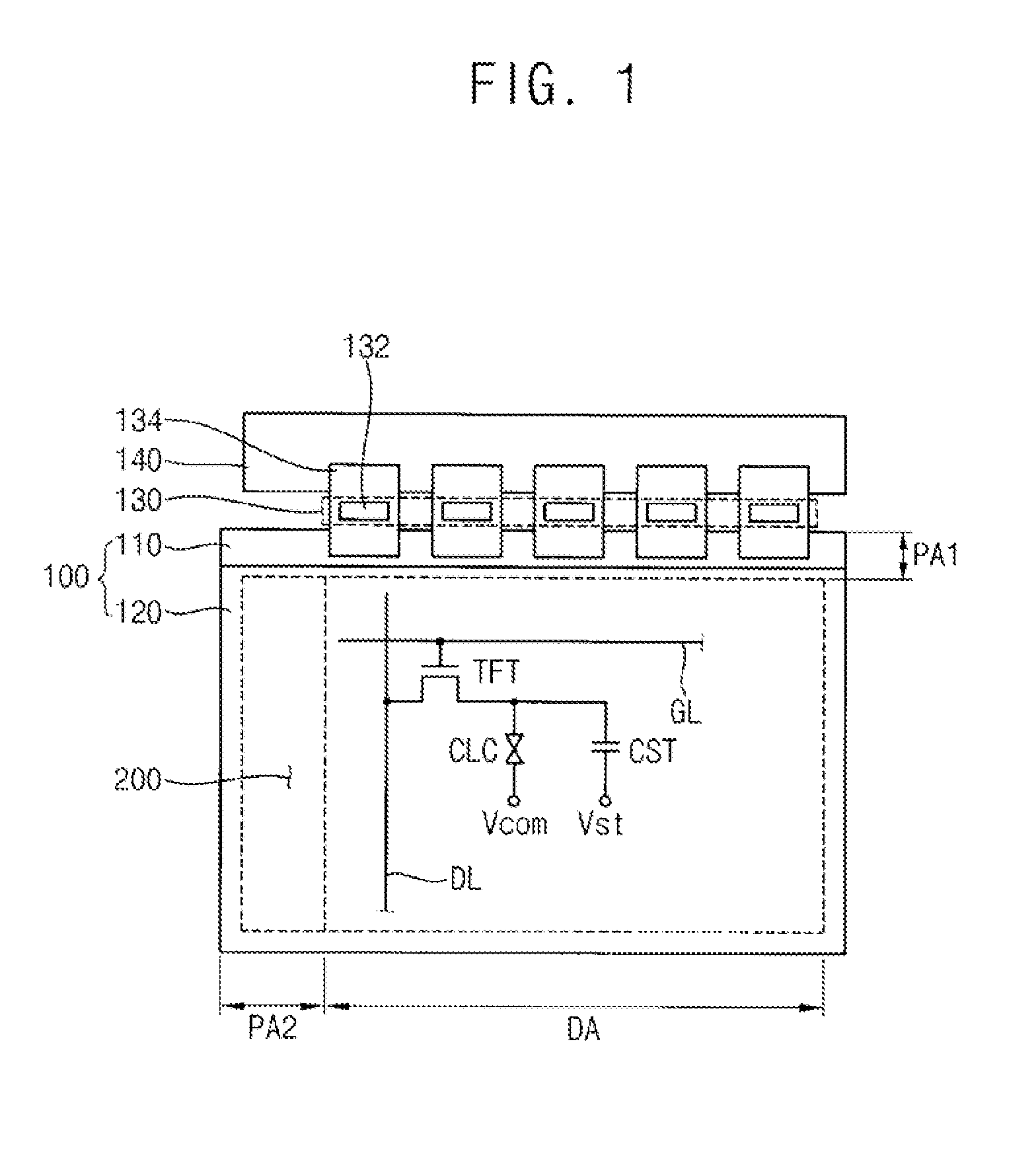
[0042]FIG. 1 is a plan view illustrating a display device according to an exemplary embodiment of the presen...


PUM


Abstract

A pull-up driving part maintains a signal of a first node at a high level by receiving a turn-on voltage in response to one of a previous stage or a vertical start signal. A pull-up part outputs a clock signal through an output terminal in response to the signal of the first node. A first holding part maintains a signal of a second node at a high level or a low level when the signal of the first node is respectively low or high. A second holding part maintains the signal of the first node and a signal of the output terminal at a ground voltage in response to the signal of the second node or a delayed and inverted clock signal.

Description

CROSS-REFERENCE TO RELATED APPLICATION[0001]This application claims priority under 35 U.S.C. §119 to Korean Patent Application No. 2008-131926, filed on Dec. 23, 2008 in the Korean Intellectual Property Office (KIPO), the contents of which are herein incorporated by reference in their entirety.BACKGROUND OF THE INVENTION[0002]1. Field of the Invention[0003]Exemplary embodiments of the present invention relate to a method of driving a gate line and a gate drive circuit for performing the method. More particularly, exemplary embodiments of the present invention relate to a method of driving a gate line having improved driving reliability, and a gate drive circuit for performing the method.[0004]2. Description of Related Art[0005]Display devices include a gate drive circuit and a switching device for generating images. To reduce manufacturing costs and the total size of a panel module for a display device, an amorphous silicon gate (ASG) technology has been applied that includes simult...

Claims


Application Information

Patent Timeline
Patent Type & Authority Applications(United States)
IPC IPC(8): G11C19/00
CPCG09G3/3677G11C19/28G09G2300/0408G02F1/133G09G3/20G09G3/36
Inventor LEE, HONG-WOOKIM, SUNG-MANLEE, JONG-HYUKLEE, JONG-HWANKIM, HYEON-HWANMOH, SANG-MOONKIM, JEONG-ILMOON, YEON-KYU
Owner SAMSUNG DISPLAY CO LTD
Why Eureka
Try Eureka