
Microphone Array Calibration Method and Apparatus

a micro-array and array technology, applied in the direction of transducer casings/cabinets/supports, transducers, electric transducers, etc., can solve the problems of increasing the price of microphones, incurring an added cost, and adding an extra cost to the manufacturing process of end products

Active Publication Date: 2010-06-24
SYNAPTICS INC
View PDF3 Cites 32 Cited by
  • Summary
  • Abstract
  • Description
  • Claims
  • Application Information

AI Technical Summary

Benefits of technology

[0003]The current invention provides a method and apparatus for real time calibration for microphone arrays that eliminates the need for microphone matching or offline microphone calibration.

Problems solved by technology

Matching microphone pairs is done during the manufacturing of the microphones, and is a time consuming process that also reduces the yield of the microphone pairs, thus increasing the price of the microphones.
This adds extra cost to the manufacturing process of the end product.
Both of the solutions used today thus incur an added cost.

Method used


Image

  • Microphone Array Calibration Method and Apparatus
  • Microphone Array Calibration Method and Apparatus
  • Microphone Array Calibration Method and Apparatus

Examples


Embodiment Construction

[0013]In the description that follows, like parts are marked throughout the specification and drawings with the same reference numerals, respectively. The drawing figures might not be to scale, and certain components can be shown in generalized or schematic form and identified by commercial designations in the interest of clarity and conciseness.

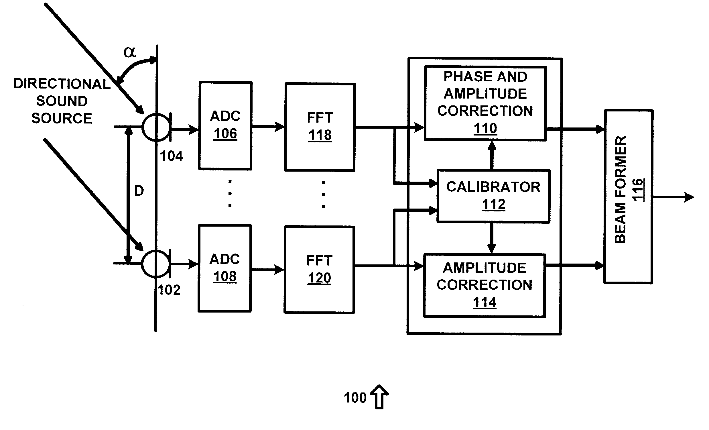
[0014]FIG. 1 is a diagram of a system 100 for equalizing the phase and amplitude of a microphone array in accordance with an exemplary embodiment of the present invention. System 100 provides real-time compensation for mismatch in the phase and amplitude characteristics of the microphones, allowing accurate beamforming, and can be used as a preprocessor to a suitable frequency domain beam-forming process to improve the accuracy and the performance of the beam-former, or for other suitable purposes.

[0015]System 100 can be implemented in hardware or a suitable combination of hardware and software, and can include one or more software systems o...


PUM


Abstract

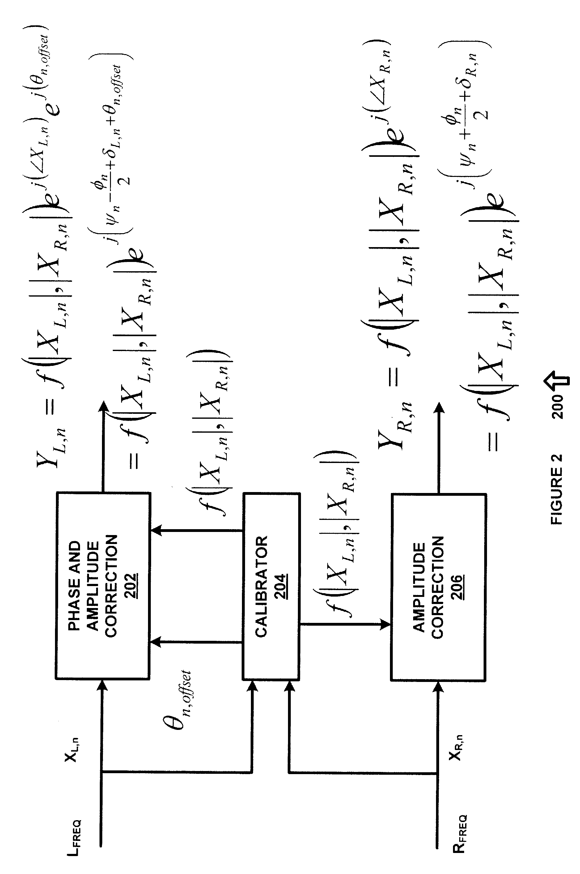
An apparatus for providing real-time calibration for two or more microphones. A calibrator for receiving a left microphone signal and a right microphone signal and generating phase difference data. A phase and amplitude correction system for receiving one of the left microphone signal or the right microphone signal the phase difference data and generating calibration data for a beamformer. The beamformer receiving the calibration data, the left microphone signal and the right microphone signal and generating a monaural beamformed signal.

Description

FIELD OF THE INVENTION[0001]The invention relates to microphone array calibration using a pair of small separation microphones, and more particularly to a micro-array beamforming method and apparatus that allow un-match microphone pairs to be used that eliminates the need for costly offline calibration process by using real time calibration based on signals received during normal use.BACKGROUND OF THE INVENTION[0002]In the past, beamforming with small separation microphones has relied on two possible solutions: 1) microphone matching, or 2) offline microphone calibration. Matching microphone pairs is done during the manufacturing of the microphones, and is a time consuming process that also reduces the yield of the microphone pairs, thus increasing the price of the microphones. Offline microphone calibration uses specific calibration signals and needs to be executed, in a quiet environment, during the manufacturing of the end product. This adds extra cost to the manufacturing proces...

Claims


Application Information

Patent Timeline
IPC IPC(8): H04R3/00
CPCH04R3/005
Inventor THORMUNDSSON, TRAUSTILAU, HARRY K.KERNER, YAIR
Owner SYNAPTICS INC
Learn More