
Integrated acoustic transducer obtained using MEMS technology, and corresponding manufacturing process

a technology of integrated acoustic transducers and manufacturing processes, applied in the direction of electrostatic transducer microphones, electrostatic transducers, semiconductor electrostatic transducers, etc., can solve the problems of significantly affecting the performance of mems microphones of a known type, reducing the sensitivity, and affecting the performance of mems microphones. , to achieve the effect of reducing the sensitivity of the microphon

Active Publication Date: 2010-06-24
STMICROELECTRONICS SRL
View PDF9 Cites 119 Cited by
  • Summary
  • Abstract
  • Description
  • Claims
  • Application Information

AI Technical Summary

Benefits of technology

The patent describes an integrated acoustic transducer made using MEMS technology. The transducer includes a substrate with a cavity, a membrane anchored to the substrate, and a membrane suspended above the cavity and fixed to the substrate through the membrane anchorage. The membrane is designed to vibrate and has a spring near the membrane anchorage that acts in tension or compression in the same plane as the membrane. The patent also describes a manufacturing process for this transducer that overcomes the limitations of existing methods. The technical effects of this invention include improved sensitivity, reduced power consumption, and reduced size of the acoustic transducer.

Problems solved by technology

MEMS microphones of a known type are, however, subject to problems deriving from residual stresses (compressive or tensile) within the layer that forms the membrane.
Residual stresses are frequently the cause of mechanical deformations of the membrane, such as for example warping or buckling, and can significantly affect the performance of the MEMS microphone, for example, reducing the sensitivity thereof.
Even though it is possible to control the amount of residual stress in the membrane by means of an appropriate design of the membrane itself and by evaluating the optimal manufacturing conditions, the result obtained is not satisfactory for applications in which a high sensitivity is required.
However, this solution is valid only in the cases in which the residual stresses in the supporting beam are small.
If, instead, the supporting beam is subjected to tensile or compressive stresses, it tends to warp in an unforeseeable way, causing a deformation or an inclination of the mobile electrode, which hence assumes a position not parallel to the fixed electrode.
There can hence occur problems of reduced sensitivity of the microphone during use, and, in more serious cases, a direct contact between the mobile electrode and the fixed electrode.

Method used


Image

  • Integrated acoustic transducer obtained using MEMS technology, and corresponding manufacturing process
  • Integrated acoustic transducer obtained using MEMS technology, and corresponding manufacturing process
  • Integrated acoustic transducer obtained using MEMS technology, and corresponding manufacturing process

Examples


Embodiment Construction

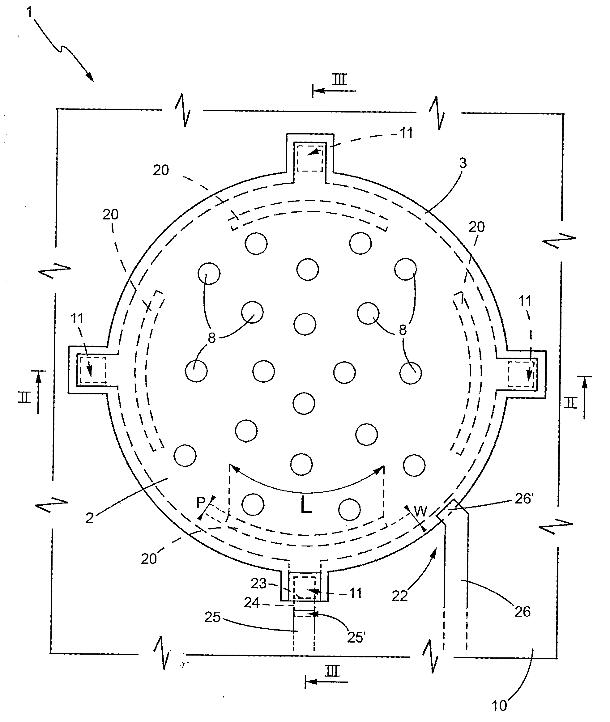
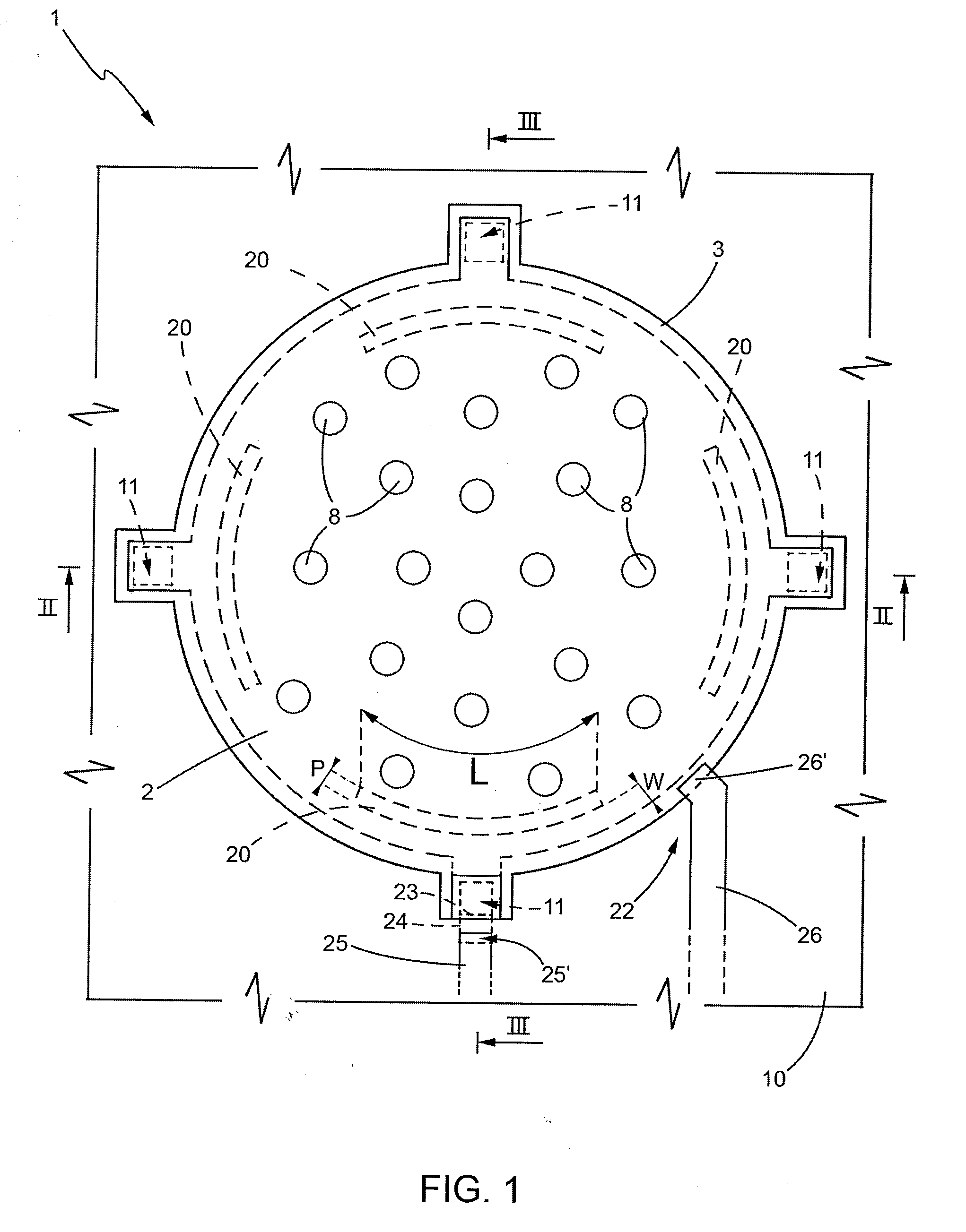
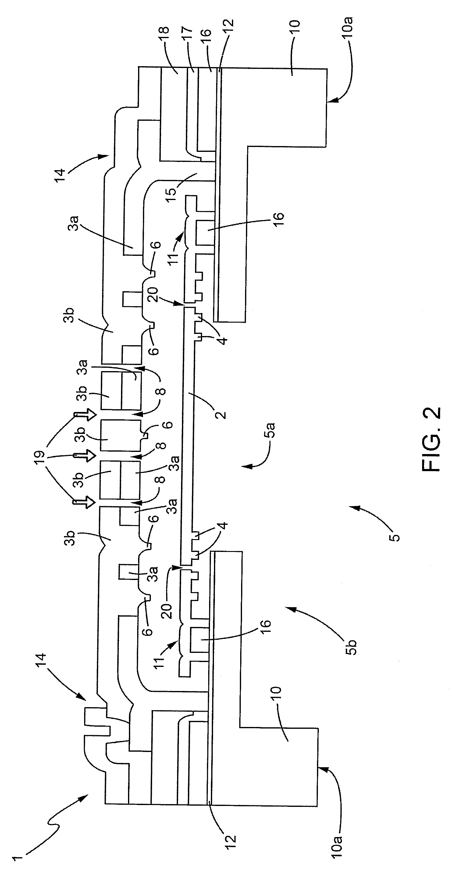
[0026]FIGS. 1-3 show, respectively, a top plan view and views in cross section of an assemblage of a membrane and a rigid plate of an integrated acoustic transducer obtained using MEMS technology, for example, a microelectromechanical microphone, according to one embodiment of the present disclosure. For reasons of simplicity, in what follows reference will be made to said assemblage generally as MEMS microphone 1, even though the electronics for supplying the microphone and for signal conditioning, are not shown and even though the description is not limited particularly to a microphone, but is valid for any acoustic transducer.

[0027]With joint reference to FIGS. 1 and 2, the MEMS microphone 1 is a microphone of a capacitive type and comprises a membrane 2, which is mobile and is made of conductive material, facing a rigid plate 3 (the so-called “back plate”), of a fixed type and formed by a first plate layer 3a, made of conductive material and facing the membrane 2, and by a secon...


PUM


Abstract

A MEMS acoustic transducer provided with a substrate having cavity, and a membrane suspended above the cavity and fixed peripherally to the substrate, with the possibility of oscillation, through at least one membrane anchorage. The membrane comprises at least one spring arranged in the proximity of the anchorage and facing it, and is designed to act in tension or compression in a direction lying in the same plane as said membrane.

Description

BACKGROUND[0001]1. Technical Field[0002]The present disclosure relates to an integrated acoustic transducer in MEMS technology and to the corresponding manufacturing process, and in particular to a microelectromechanical (MEMS) microphone of a capacitive type.[0003]2. Description of the Related Art[0004]As is known, an acoustic transducer, for example, a MEMS microphone, of a capacitive type generally comprises a mobile electrode, in the form of a diaphragm or membrane, arranged facing a fixed electrode, to provide the plates of a capacitor. The mobile electrode is generally anchored, by means of a perimetral portion thereof, to a substrate, whilst a central portion thereof is free to move or bend in response to a pressure of sound wave acting on a surface of the mobile electrode. Since the mobile electrode and the fixed electrode form a capacitor, bending of the membrane that constitutes the mobile electrode causes a variation of capacitance of the capacitor. In use, said variation...

Claims


Application Information

Patent Timeline
Patent Type & Authority Applications(United States)
IPC IPC(8): H04R25/00
CPCH04R7/24H04R31/00H04R19/04H04R19/005
Inventor CONTI, SEBASTIANOPERLETTI, MATTEO
Owner STMICROELECTRONICS SRL
Learn More