
Image encoding apparatus and control method thereof

a technology of image data and encoding apparatus, applied in electrical apparatus, instruments, computing, etc., can solve the problems of inability to perform encoding, inconvenient decoding only a specific region, and image quality degradation around tile boundaries, so as to prevent the degradation of image quality in the specific region, suppress segmentation, and suppress the effect of segmentation

Inactive Publication Date: 2010-06-24
CANON KK
View PDF1 Cites 29 Cited by
  • Summary
  • Abstract
  • Description
  • Claims
  • Application Information

AI Technical Summary

Benefits of technology

The present invention provides a technique for performing encoding by tile while suppressing segmentation of a specific region in an image into tiles, using a smallest possible tile size. This results in improved image quality in the tile boundary and prevents degradation of image quality in the specific region due to segmentation. Additionally, upon partial decoding, as it is possible to set a tile size in consideration of a range influenced by filter processing or the like, the degradation of image quality in the specific region can be suppressed.

Problems solved by technology

However, because a tile size is fixed in the conventional image encoding, it is inconvenient to efficiently decode only a specific region.
Further, when filter processing is performed over tiles, in the case of partial decoding by each tile, the image quality is degraded around tile boundaries.
However, although methods for determining a cell size in correspondence with one object as in the case of the above-described method are known, a method for setting a tile in a smallest possible size for plural objects and performing encoding has not been proposed.

Method used


Image

  • Image encoding apparatus and control method thereof
  • Image encoding apparatus and control method thereof
  • Image encoding apparatus and control method thereof

Examples


first embodiment

[0038]In the first embodiment, a tile boundary is set based on positional relation among face detection results, and thereby two or more face regions are respectively set within a smallest possible sized tile. Further, for the sake of simplification of explanation, the description of the embodiment will be made on the presupposition that an image encoding apparatus in the present embodiment is incorporated in an image capturing apparatus such as a digital camera.

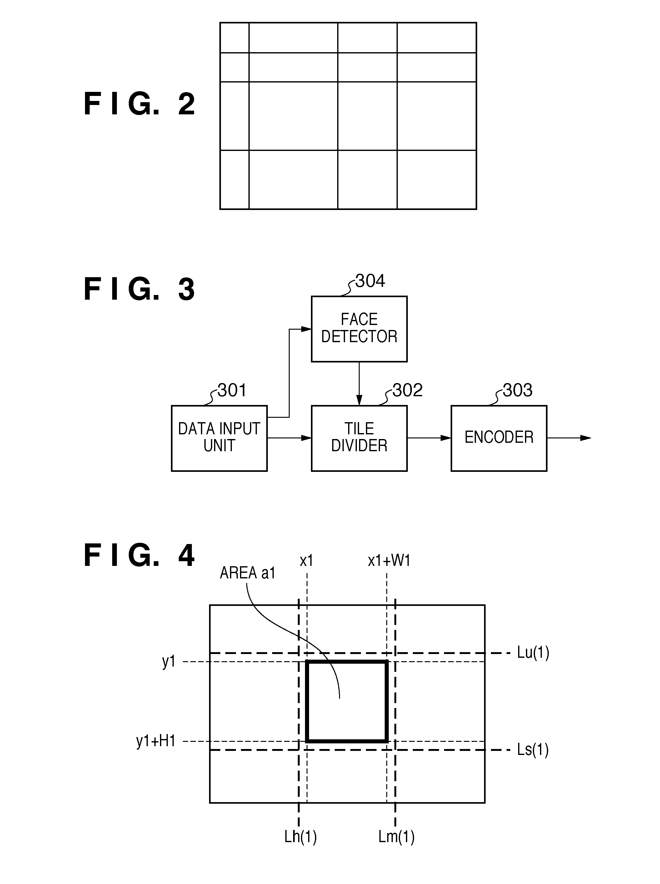
[0039]FIG. 3 is a block diagram of the image encoding apparatus according to the first embodiment.

[0040]As shown in FIG. 3, the image encoding apparatus according to the present embodiment has a data input unit 301, a tile divider 302, an encoder 303 and a face detector 304.

[0041]The data input unit 301 inputs image data obtained by an image sensing device of the digital camera. The face detector 304 detects a face region (specific region) of a person in the input image data, and outputs information regarding the detected re...

second embodiment

[0084]In the first embodiment, a smallest possible size is set for a tile including a face region with its tile boundaries not crossing any other face region. In the second embodiment, crossing of some tile boundaries in face regions is permitted.

[0085]As an example where the crossing of tile boundaries in some face regions is permitted, given is a case where a large number of faces are detected and the size of a tile set by the method in the first embodiment is very large.

[0086]For example, in a group photograph shown in FIG. 9, many face regions exist, and some of the face regions overlap each other. Otherwise, in a non-overlapped face region, a tile boundary candidate line crosses another face region and the tile boundary is an end of the image, thereby the image cannot be subjected to tile division.

[0087]In this case, to efficiently perform tile division and encoding, it is necessary to automatically prioritize the detected face regions in the obtained photograph and determine a...

third embodiment

[0105]Next, in the third embodiment, an encoding method will be described regarding a case where tile boundaries are set and the tile has large blank space in the first and second embodiments.

[0106]For example, when tile boundaries are set as shown in an image 602 in FIG. 6A, the area a1 is in an upper position in the tile and the area a2 is in a lower position in the tile. Accordingly, even only the tiles including face regions are extracted and subjected to decoding processing, unnecessary portions are also processed.

[0107]In this case, as regions to be processed other than the face regions as objects of processing are increased, the processing speed is lowered.

[0108]When a face region exists on the lower side in a tile, upon encoding, the coordinate value of the detected face region is added as a pointer to coded data, thereby the processing can be started from the head of the face region without processing blank space.

[0109]Further, when the face region exists on the upper side ...


PUM


Abstract

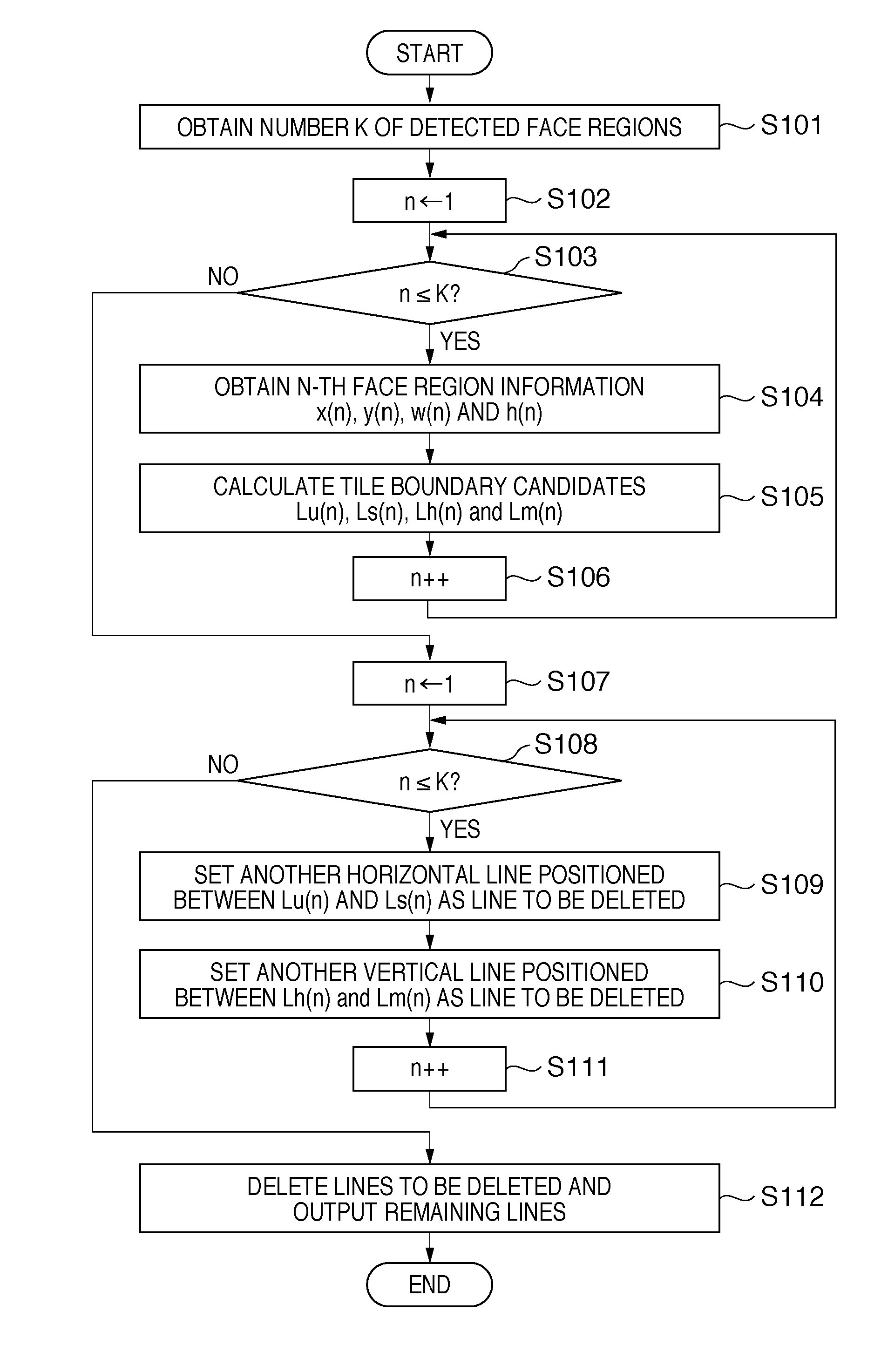
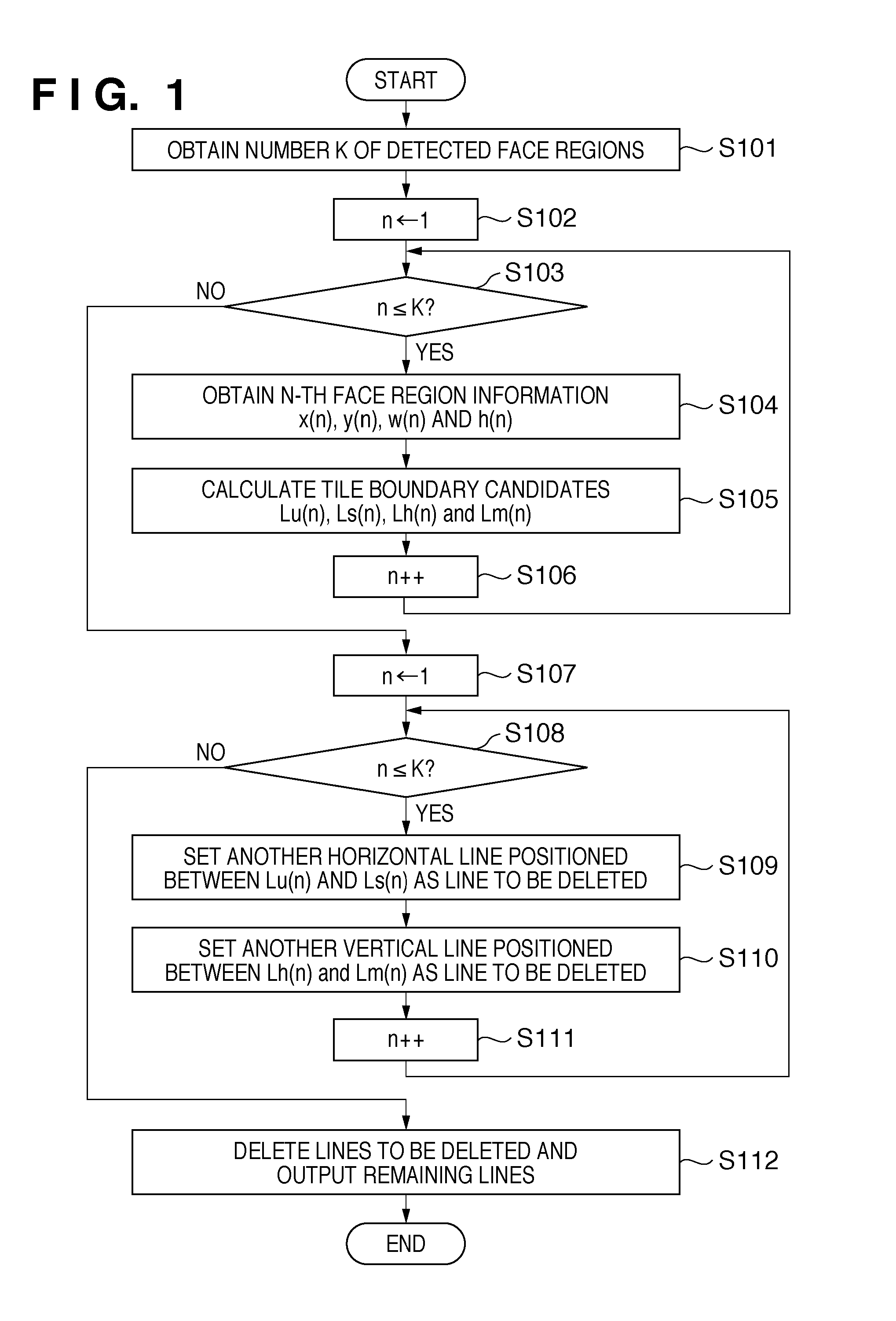
An encoding apparatus encodes an image by tile in a smallest possible size while suppresses segmentation of a specific region in the image into tiles. Vertical lines at left and right ends of n-th face region are defined as boundary candidate vertical lines Lh(n) and Lm(n), and horizontal lines at upper and lower ends of the n-th region, as boundary candidate horizontal lines Lu(n) and Ls(n). A divider determines a horizontal line of another region existing within the range of the horizontal lines Lu(n) and Ls(n) of the n-th region as a line to be deleted. Further, the divider determines a vertical line of another region existing within the range of the vertical lines Lh(n) and Lm(n) as a line to be deleted. This processing is performed to the final region, then image data is divided using horizontal and vertical lines except the lines determined as lines to be deleted.

Description

BACKGROUND OF THE INVENTION[0001]1. Field of the Invention[0002]The present invention relates to a technique for encoding image data.[0003]2. Description of the Related Art[0004]A technique of dividing a still image into tiles and encoding the image by tile is known. For example, as one function in JPEG 2000 (ISO / ITU 15444-1:2000), tile division processing for dividing an image into small regions and independently encoding the small regions is adopted. Note that because the details of the JPEG 2000 method are described in international standard recommendations and the like, the details will be omitted here.[0005]Because an image region can be specified by tile, it is possible, when executing tile division processing, to decode only a tile to be processed without processing regions other than the tile to be processed in an encoded state. Thus, image editing and image processing can be performed on only the tile to be processed.[0006]However, because a tile size is fixed in the conven...

Claims


Application Information

Patent Timeline
Patent Type & Authority Applications(United States)
IPC IPC(8): G06K9/46H04N1/41H04N19/00H04N19/119H04N19/167H04N19/625H04N19/91
CPCG06K9/00228H04N19/70H04N19/17H04N19/46H04N19/60H04N19/119G06V40/161
Inventor SHIRAISHI, YUKIYAMAZAKI, TAKESHI
Owner CANON KK
Learn More