
Robot and method of controlling the same

a robot and control method technology, applied in the field of robots, can solve the problems of difficult to define the limit cycle control angle of the biped robot on the three-dimensional space, dangerous work performed by the robot, and large force,

Active Publication Date: 2010-06-24
SAMSUNG ELECTRONICS CO LTD
View PDF4 Cites 10 Cited by
  • Summary
  • Abstract
  • Description
  • Claims
  • Application Information

AI Technical Summary

Benefits of technology

[0017]The control of the limit cycle control angles using the sinusoidal function may be achieved such that relations of the limit cycle control angles and control angular velocities, which are differential components of the limit cycle control angles, form the limit cycle in the stable closed loop on the space.
[0018]The angles of the ankles of the robot may be controlled within the limit cycle by controlling the limit cycle control angles using the sinusoidal function.
[0019]The foregoing and / or other aspects of the present invention are achieved by providing a robot including ankles; a set unit to set limit cycle control angles of the ankles on a three-dimensional space; and a control unit to control the set limit cycle control angles on the three-dimensional space using a sinusoidal function and thus control the angles of the ankles within a limit cycle using the sinusoidal function.
[0020]The set unit may set the limit cycle control angles in consideration of position, direction, tilt data of the robot on the three-dimensional space to balance the robot.
[0021]The control unit may control the limit cycle control angles using the sinusoidal function such that the limit cycle forms a stable closed loop on the three-dimensional space.
[0022]The control unit may control the angles of the ankles within the limit cycle by controlling the limit cycle control angles using the sinusoidal function.

Problems solved by technology

These robots performed dangerous work, simple repetitive work, or work requiring large forces, in place of a human being.
However, since a biped robot on a three-dimensional space has joints with different positions and directions, it is not easy to define limit cycle control angles of the biped robot on the three-dimensional space.

Method used


Image

  • Robot and method of controlling the same
  • Robot and method of controlling the same
  • Robot and method of controlling the same

Examples


Embodiment Construction

[0034]Reference will now be made in detail to the embodiment of the present invention, an example of which is illustrated in the accompanying drawings, wherein like reference numerals refer to like elements throughout. The embodiment is described below to explain the present invention by referring to the annexed drawings.

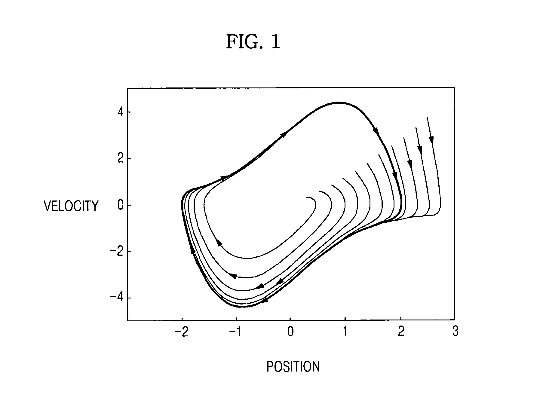
[0035]FIG. 1 is a view illustrating the concept of a limit cycle applied to the present invention and FIG. 2 is a schematic view illustrating the external appearance of a robot in accordance with an embodiment of the present invention.

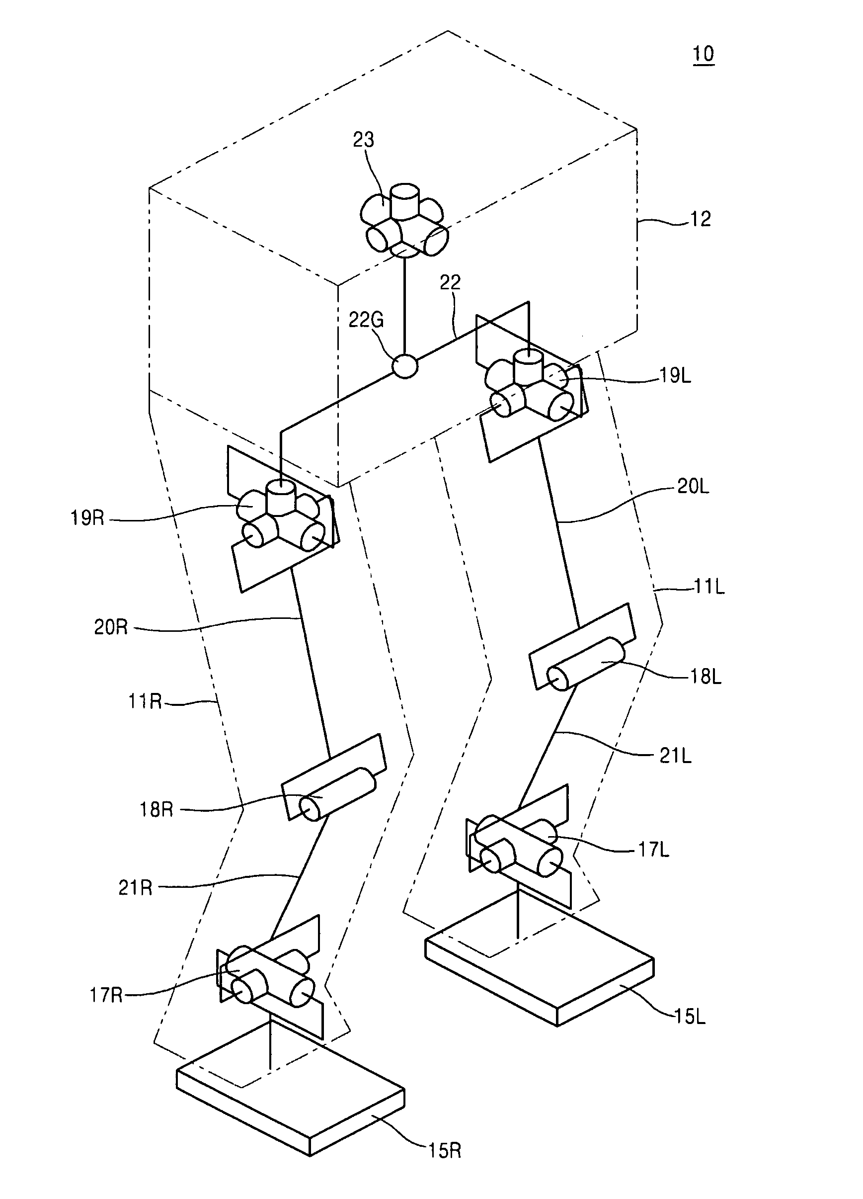
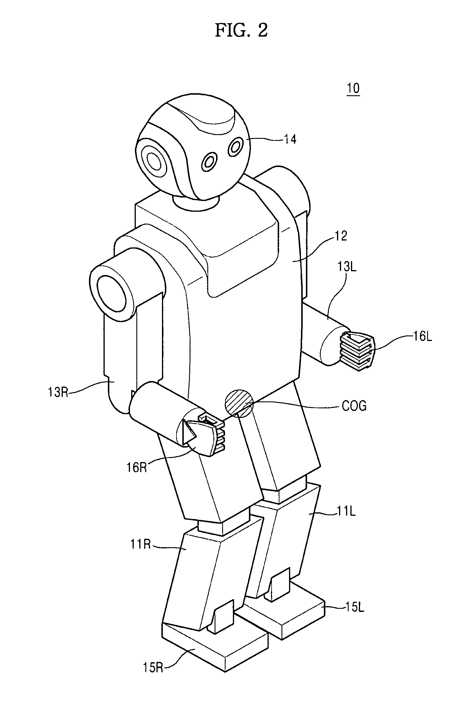
[0036]In FIG. 2, a robot 10 in accordance with this embodiment is a biped walking robot, which walks upright with two legs 11R and 11L in the same way as a human being, and includes a torso 12, two arms 13R and 13L and a head 14 provided at the upper portion of the torso 12, and feet 15R and 15L and hands 16R and 16L respectively provided at tips of the two legs 11R and 11L and the two arms 13R and 13L.

[0037]Here, R represents the righ...


PUM


Abstract

Disclosed is a method of defining control angles to use a limit cycle in order to balance a biped walking robot on a three-dimensional space. In order to balance an FSM-based biped walking robot right and left on a three-dimensional space, limit cycle control angles to balance the robot according to states of the FSM-based robot are set on the three-dimensional space, and the limit cycle control angles on the three-dimensional space are controlled using a sinusoidal function to allow relations between the control angles and control angular velocities to form a stable closed loop within a limit cycle.

Description

CROSS-REFERENCE TO RELATED APPLICATIONS[0001]This application claims the benefit of Korean Patent Application No. 2008-0131033, filed Dec. 22, 2008, in the Korean Intellectual Property Office, the disclosure of which is incorporated herein by reference.BACKGROUND[0002]1. Field[0003]The present invention relates to a robot and a method of controlling the same, and more particularly, to a method of defining control angles to use a limit cycle in order to balance a biped walking robot on a three-dimensional space.[0004]2. Description of the Related Art[0005]In general, machines, which conduct motions similar to those of a human being using an electrical or magnetic action, are known as robots. Early robots were industrial robots, such as manipulators or transfer robots, for work automation and unmanned operation in a production field. These robots performed dangerous work, simple repetitive work, or work requiring large forces, in place of a human being. Recently, biped walking robots,...

Claims


Application Information

Patent Timeline
Patent Type & Authority Applications(United States)
IPC IPC(8): G06F19/00
CPCB62D57/032B25J9/1628B25J9/1612B25J9/162G05B2219/36424
Inventor KWAK, HO SEONGKWON, WOONGROH, KYUNG SHIK
Owner SAMSUNG ELECTRONICS CO LTD
Learn More