
Data recording program, data recording apparatus, data recording process, and recording medium

a data recording and data technology, applied in static indicating devices, instruments, cad techniques, etc., can solve the problems of large amount of data of sequential outputted calculation results, large processing time for displaying huge amount of data, and large areas for storing calculations

Inactive Publication Date: 2010-06-24
FUJITSU LTD
View PDF7 Cites 5 Cited by
  • Summary
  • Abstract
  • Description
  • Claims
  • Application Information

AI Technical Summary

Problems solved by technology

Therefore, the amount of data of the sequentially outputted calculation results becomes huge.
However, the processing time for displaying the huge amount of data also becomes huge.
As explained above, programs (such as simulation programs) which output a great amount of calculation results and perform analysis on the basis of the calculation results require a long processing time and great areas for storing calculation results.
However, it is difficult to appropriately set the intervals at which the data obtained by performing simulation are thinned out.
That is, in some cases where the thinning-out intervals are great, data in a time interval of interest or a spatial region of interest can be lost, i.e., necessary data can be lost.
On the other hand, in the case where the thinning-out intervals are small, the amount of data cannot be greatly reduced.
In addition, in the case where the technique disclosed in Japanese Laid-open Patent Publication No. 2000-206105 is applied to a simulation of a phenomenon in a physical space with a large-scale model as mentioned before, and the spatial variation rates (the X-, Y-, and Z-axes in a three-dimensional space) and timewise variation rates (along the time axis) are obtained on a point-by-point basis in the physical space, the burden of calculation greatly increases since the handled data are multidimensional.

Method used


Image

  • Data recording program, data recording apparatus, data recording process, and recording medium
  • Data recording program, data recording apparatus, data recording process, and recording medium
  • Data recording program, data recording apparatus, data recording process, and recording medium

Examples


Embodiment Construction

)

[0028]An embodiment of the present invention will be explained below with reference to the accompanying drawings, wherein like reference numerals refer to like elements throughout. First, an outline of the embodiment is explained, and then details of the embodiment are explained.

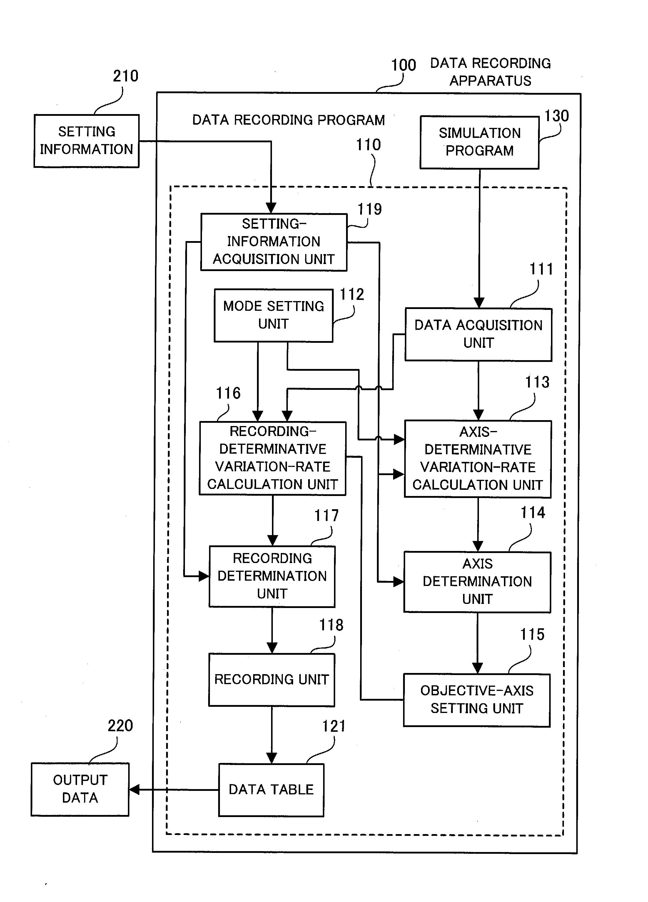
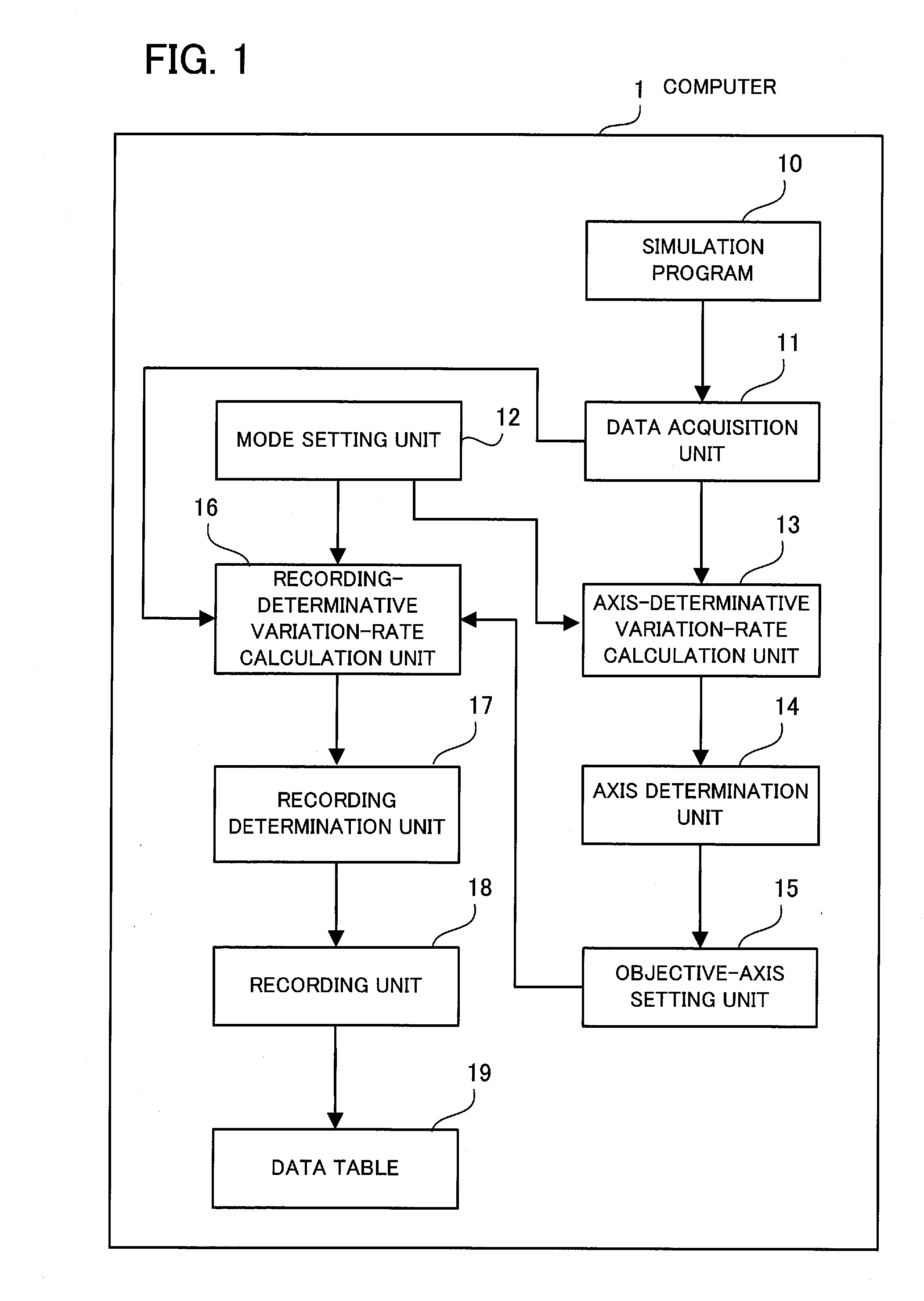
[0029]FIG. 1 is a diagram illustrating the outline of the embodiment. The computer 1 illustrated in FIG. 1 can save the storage capacity necessary for storing data, and reduce the burden of calculation performed for decreasing the number of data items, where the data is obtained by calculation by a simulation program 10 or the like, and varies in a multidimensional space constituted by a plurality of dimensional axes. The computer 1 comprises a data acquisition unit 11, a mode setting unit 12, an axis-determinative variation-rate calculation unit 13, an axis determination unit 14, an objective-axis setting unit 15, a recording-determinative variation-rate calculation unit 16, a recording determination unit ...


PUM


Abstract

The data acquisition unit acquires data in correspondence with each dimensional axis and the time axis. The mode setting unit makes setting and clearing of a dimensionality investigation mode. In the dimensionality investigation mode, the axis-determinative variation-rate calculation unit calculates axial data variation rates. The axis determination unit determines whether or not the axial data variation rate corresponding to each axis is low. The objective-axis setting unit sets each axis as an objective axis when the axial data variation rate corresponding to the axis is determined to be high. While the dimensionality investigation mode is cleared, the recording-determinative variation-rate calculation unit calculates axial data variation rates. The recording determination unit determines, on the basis of the axial data variation rate, whether to record the acquired data. The recording unit does not record the data when the data is determined not to be recorded.

Description

[0001]This application is a continuing application, filed under 35 U.S.C. §111(a), of International Application PCT / JP2007 / 067178, filed Sep. 4, 2007.FIELD[0002]The embodiment discussed herein is related to a data recording program, a data recording apparatus, and a data recording process.BACKGROUND[0003]In large-scale simulations such as molecular simulation and global warming simulation, one or more physical quantities are calculated and outputted at every timestep. Therefore, the amount of data of the sequentially outputted calculation results becomes huge.[0004]Specifically, the amount of data outputted as above can be represented by the product of the mesh size in the physical space in which the calculation is performed, the number of timesteps, and the number of handled physical quantities. For example, in the model in which the mesh size in a three-dimensional space is 10,000×10,000×10,000, and the number of timesteps indicating the elapse of time is 100,000, and the number o...

Claims


Application Information

Patent Timeline
Patent Type & Authority Applications(United States)
IPC IPC(8): G06F17/30
CPCG06F2217/16G06F17/5009G06F2111/10G06F30/20
Inventor INADA, YOSHIE
Owner FUJITSU LTD
Learn More