Interlocking modular flooring assembly with bevelled connectors

a technology of modular flooring and connectors, which is applied in the field of floor coverings, can solve the problems of affecting the service life of the floor covering, so as to achieve the effect of ensuring the installation of the floor covering in this fashion, and reducing the labor intensity of the installation

Inactive Publication Date: 2010-07-01
ANI MAT
View PDF12 Cites 11 Cited by
  • Summary
  • Abstract
  • Description
  • Claims
  • Application Information

AI Technical Summary

Benefits of technology

[0011]The mat units are preferably made of a semi-rigid material, such as recycled rubber or the like. The semi-rigid material should provide enough rigidity for the target heavy-duty application while allowing enough deformability of the teeth to engage them in the grooves of an adjacent mat unit.
[0015]Advantageously, embodiments of the present invention provide a flooring assembly in which adjacent mat units are strongly interlocked so as to remain so in use without the need for nailing or otherwise affixing the mat units to the ground.

Problems solved by technology

In the context of indoor or outdoor installations of livestock operations, animals may spend several hours on non-natural and very hard floors, which can be hurtful to them.
A common problem encountered with the prior art flooring assembly is the “waving” phenomenon which occurs when external elements such as sand of liquid penetrate the joint between two adjacent mats units and accumulate under the flooring and thus form a “wave”.
When, for instance, machinery or livestock passes on the flooring it can displace the “wave” and eventually disconnect or break the mat unit.
Obviously this deterioration of the joints weakens the flooring assembly and increases the risk that someone or something comes up against the exposed teeth and definitely damage the flooring assembly.
However, securing mat units in this fashion is labour intensive and protruding nails or screws present an injury risk for the livestock.
Furthermore, the installation of such flooring with attachment means can damage existing facilities, for example a heating floor or water pipes embedded in the flooring.

Method used


Image

  • Interlocking modular flooring assembly with bevelled connectors
  • Interlocking modular flooring assembly with bevelled connectors
  • Interlocking modular flooring assembly with bevelled connectors

Examples


Embodiment Construction

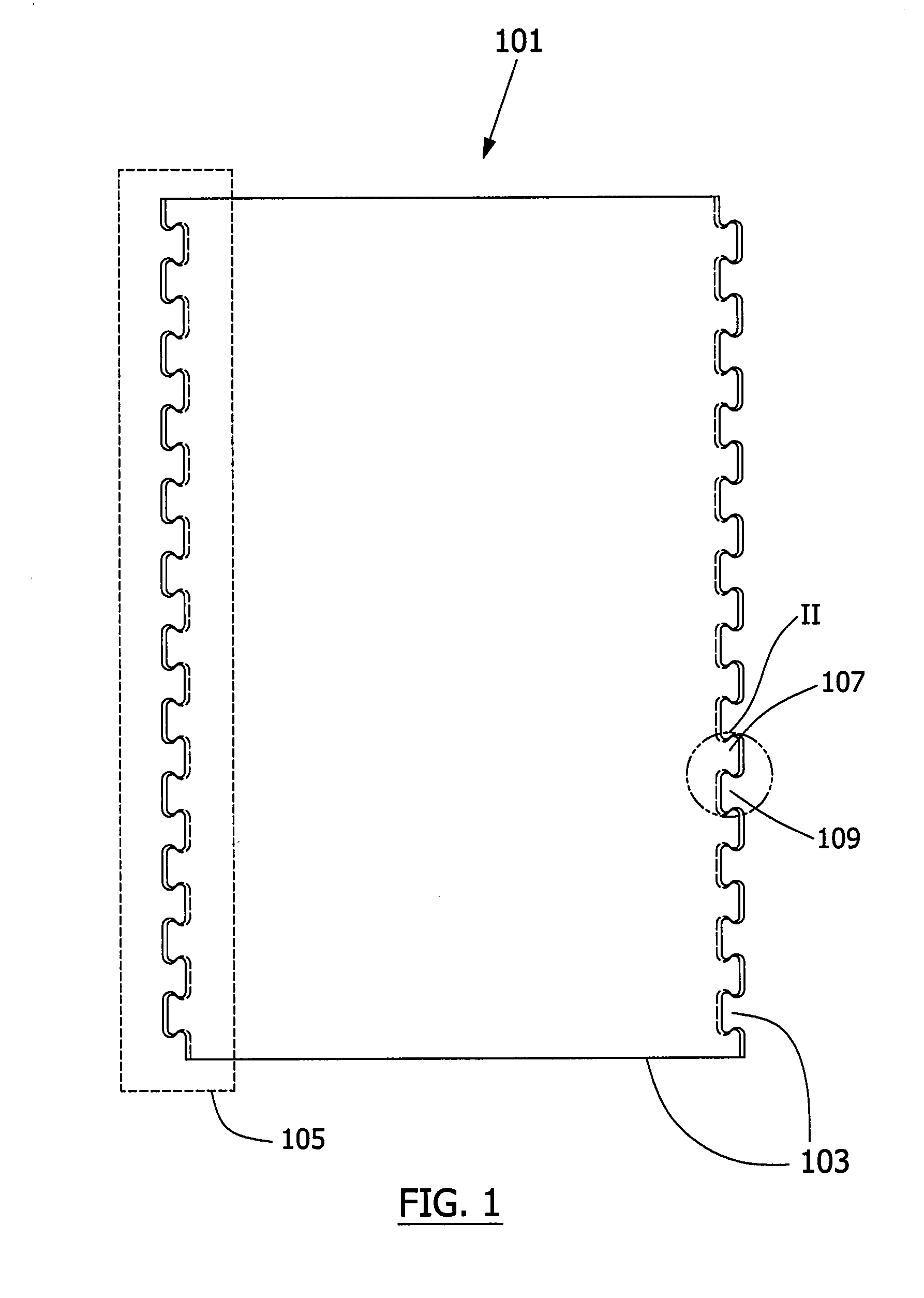
[0024]The present invention provides a modular flooring assembly for heavy-duty applications. The expression “heavy-duty” is understood herein to refer to applications where the flooring assembly is subjected, at least occasionally, to strain or forces which tend to move or deforms the individual mat units or disengage neighbouring units. Such an application for example includes farming environments, in particular dairy farms, where such flooring assemblies are used in livestock facilities where cows or other animals are often confined for extended periods of time. Other heavy-duty applications may include garages, warehouses and also gymnasium or other sportive locations.

[0025]Referring to FIG. 5, there is shown a modular flooring assembly 100 according to an embodiment of the invention. The flooring assembly 100 includes a plurality of interlocked mat units 101. By “modular”, it is meant that the mat units 101 are designed such that each unit 101 can be connected with identical or...


PUM

PropertyMeasurementUnit
angleaaaaaaaaaa
angleaaaaaaaaaa
angleaaaaaaaaaa

Abstract

A modular flooring assembly for heavy-duty applications is presented. It is made of a plurality of interlockable mat units, each mat having a plurality of edges with at least one edge having a connector in the plane of the mat unit. Each connector is made of a plurality of alternating teeth and grooves respectively adapted to engage the grooves and the teeth of another mat unit. Each groove has a first bevel with respect to the plane extending along its back wall and a rear portion of its corresponding side walls. Each tooth has a second bevel with respect to the plane extending along its front wall and a front portion of its corresponding side walls. The first and the second bevels are complementary and each side wall form a twist transition between the first and second bevels.

Description

FIELD OF THE INVENTION[0001]The present embodied invention relates to the field of flooring surfaces and more particularly concerns a modular flooring assembly and mat units for such an assembly, such as rubber mats for livestock and the like.BACKGROUND[0002]In the context of indoor or outdoor installations of livestock operations, animals may spend several hours on non-natural and very hard floors, which can be hurtful to them. It is now well established that it is preferable to overlay hard floor surfaces of livestock housings with smooth flooring material to solve this problem.[0003]Flooring assemblies for this purpose are well-known in the art and usually involve individual interlocking mat units. The assembly of such individual mat unit allows the construction of flooring which may be easily adapted to surfaces of various sizes and shapes.[0004]It is generally desirable to be able to interlock adjacent mat units such that they remain tightly attached and form a uniform outer su...

Claims


Application Information

Patent Timeline
Patent Type & Authority Applications(United States)
IPC IPC(8): E04B5/00E04F15/22
CPCA01K1/0157E01C5/20E04F15/10E04F2201/091E04F2201/095E04F15/02172
Inventor ALLARD, ANGE ALBERTSAVARY, PIERRETREMBLAY, FREDERICLAMONTAGNE, DAVID
Owner ANI MAT
Why Eureka
Try Eureka