
Row clutch device for planting implement

a technology of planting implements and clutches, which is applied in the field of planting implements, can solve the problems of reducing yield, unfavorable conditions, and farmers experiencing economic losses, and achieve the effect of eliminating error-prone manual operation

Active Publication Date: 2010-07-01
LEADER TECH
View PDF5 Cites 30 Cited by
  • Summary
  • Abstract
  • Description
  • Claims
  • Application Information

AI Technical Summary

Benefits of technology

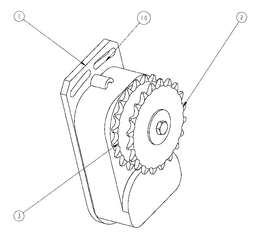
[0011]The present invention consists of apparatus including an electrically controlled clutch for controlling the operation of a seed meter of a planter implement. The clutch is interposed between an input drive chain driven by a drill shaft of the planter and an output drive chain that drives the seed meter. The clutch is located inside the row unit of the planter where it is protected against contact with and damage by debris thrown up by the planter during use. The apparatus allows direct control over planting by the seed meter of each individual row unit. Electrical energy for operating the clutches is amply provided by the standard electrical systems of tractors used in pulling and powering the planter implement. Retrofitting of existing planter implements to use the present invention is fast and easy. Further, repair or replacement of the clutches does not require removal of the drill shaft as is often required in known planter control apparatus.

Problems solved by technology

However, one undesired condition that gets worse as planter width increases is overlap.
Farmers experience economic loss in overlap areas because seed is wasted and yield is reduced compared to non-overlap areas.
Extra plants in overlap areas take soil nutrients and moisture from the intended plants, which results in reduced yield compared to non-overlap areas.
A big disadvantage is that the clutch is exposed to flying debris from planter lift wheels.
In practice, most operators find it difficult to do this accurately because the planter is moving and they need to observe other machine functions.
More planter sections make the task more difficult.

Method used


Image

  • Row clutch device for planting implement
  • Row clutch device for planting implement
  • Row clutch device for planting implement

Examples


Embodiment Construction

[0019]Illustrated in FIG. 3, generally at 20, is an eight-row planter implement that has a transversely extended tool bar 22 on which is mounted eight row units 24 for planting eight rows of seed simultaneously in a field. Each row unit 24 includes a clutch assembly 26 interposed between a seed meter 28 and the drill shaft 8. The drill shaft 8 is mounted parallel to the tool bar 22 and is rotated by a ground supported drive wheel 32 at a rate proportional to the speed of the planter implement 20 as it is drawn across a field. Each row unit 24 is mounted to the tool bar 22 using a parallel linkage system 34 to allow the row units 24 to float up and down relative to the tool bar 22.

[0020]FIGS. 4 and 6 depict individual row units 24 with parts broken away to show the interior components. A lower bar of the parallel linkage 34 is illustrated at 7. For each row unit 24, mounted on the drill shaft 8 is a driving sprocket 5 that is rotated by the drill shaft 8 at a speed proportional to th...


PUM


Abstract

Disclosed is a control apparatus for a planter implement having a drill shaft and at least one row unit including a seed meter. A clutch unit is mounted inside the row unit so that it is protected against contact and damage by crop debris and other material passing by the planting implement. An input of the clutch driven off of the drill shaft of the planting implement and an output of the clutch is operably connected to the seed meter so that operation of the clutch unit interrupts dispensing of seed by the seed meter. The clutch unit is controlled by an electrical control system to limit or prevent overlap of seed being planted by the planting implement.

Description

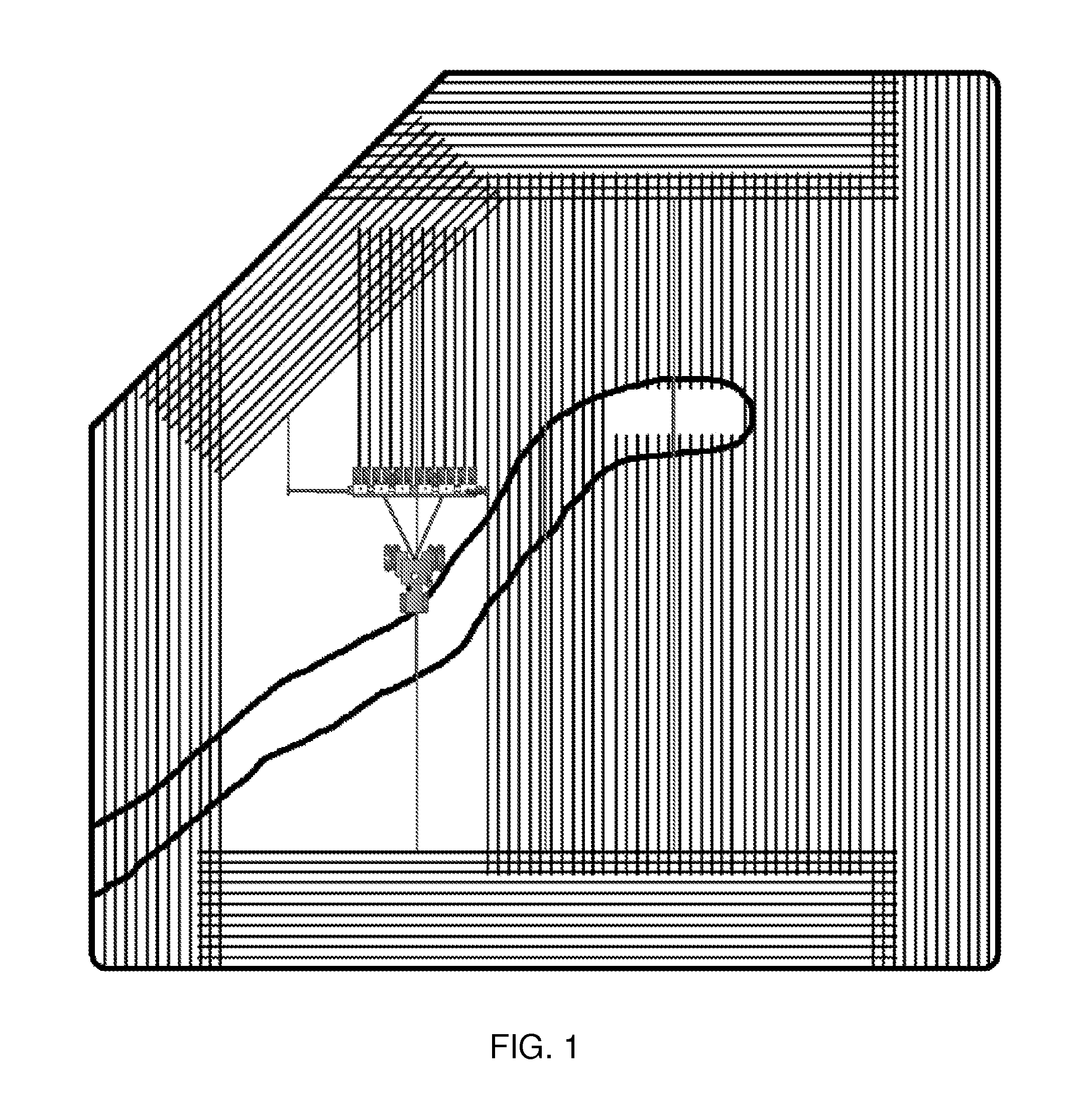
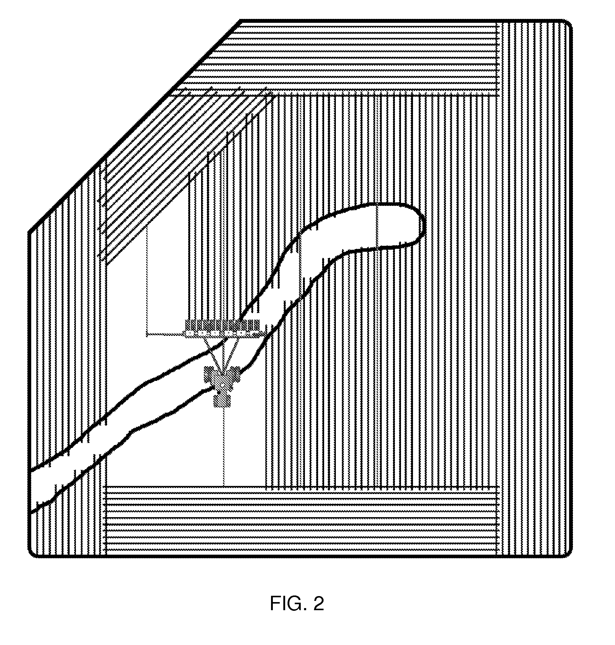
CLAIM OF PRIORITY TO RELATED APPLICATIONS[0001]This application claims priority to U.S. Patent Application Ser. No. 61 / 141,374, filed Dec. 30, 2008.BACKGROUND OF THE INVENTION[0002]The invention relates generally to planting implements and, more specifically, to a clutch that controls the operation of a seed meter on a planting implement to reduce planter overlap.[0003]In many parts of the world row crops must be planted in a short timeframe to achieve maximum yield. Farmers seeking to expand their cropland must do it without expanding the duration of planting beyond the optimum time period. Because farmers find it more efficient to use a wider planter instead of adding another planter and operator, planter manufacturers have expanded row crop planter widths. However, one undesired condition that gets worse as planter width increases is overlap.[0004]Overlap occurs each time planter passes intersect (FIG. 1). Wider planters produce greater overlap because all rows are planting whene...

Claims


Application Information

Patent Timeline
IPC IPC(8): A01G1/00
CPCA01C7/102A01C19/00
Inventor CANNON, WILLVAN DRIMMELEN, THEODORE
Owner LEADER TECH
Learn More