Flat loop Heat pipe

a heat pipe and loop technology, applied in indirect heat exchangers, reinforcing means, lighting and heating equipment, etc., can solve the problems of difficult activation of thermal dissipation circulation and over-great pressure, and achieve the effect of enhancing the heat-dissipation performance of flat lhp

Inactive Publication Date: 2010-07-01
CHIN CHI TE
View PDF5 Cites 32 Cited by
  • Summary
  • Abstract
  • Description
  • Claims
  • Application Information

AI Technical Summary

Benefits of technology

[0009]In light of the above structure, vapors generated from the working fluid under a heat source of relatively low wattage can still travel to the evaporation room, such that the flow resistance of the vapors is too little to cause overgreat pressure partially inside the evaporation room and to make it difficult for activating the circulation of thermal dissipation. Besides, the second capillary core is stoppe...

Problems solved by technology

In light of the above structure, vapors generated from the working fluid under a heat source of relatively low wattage can still travel to the evaporation room, such that the flow...

Method used


Image

  • Flat loop Heat pipe
  • Flat loop Heat pipe
  • Flat loop Heat pipe

Examples


Embodiment Construction

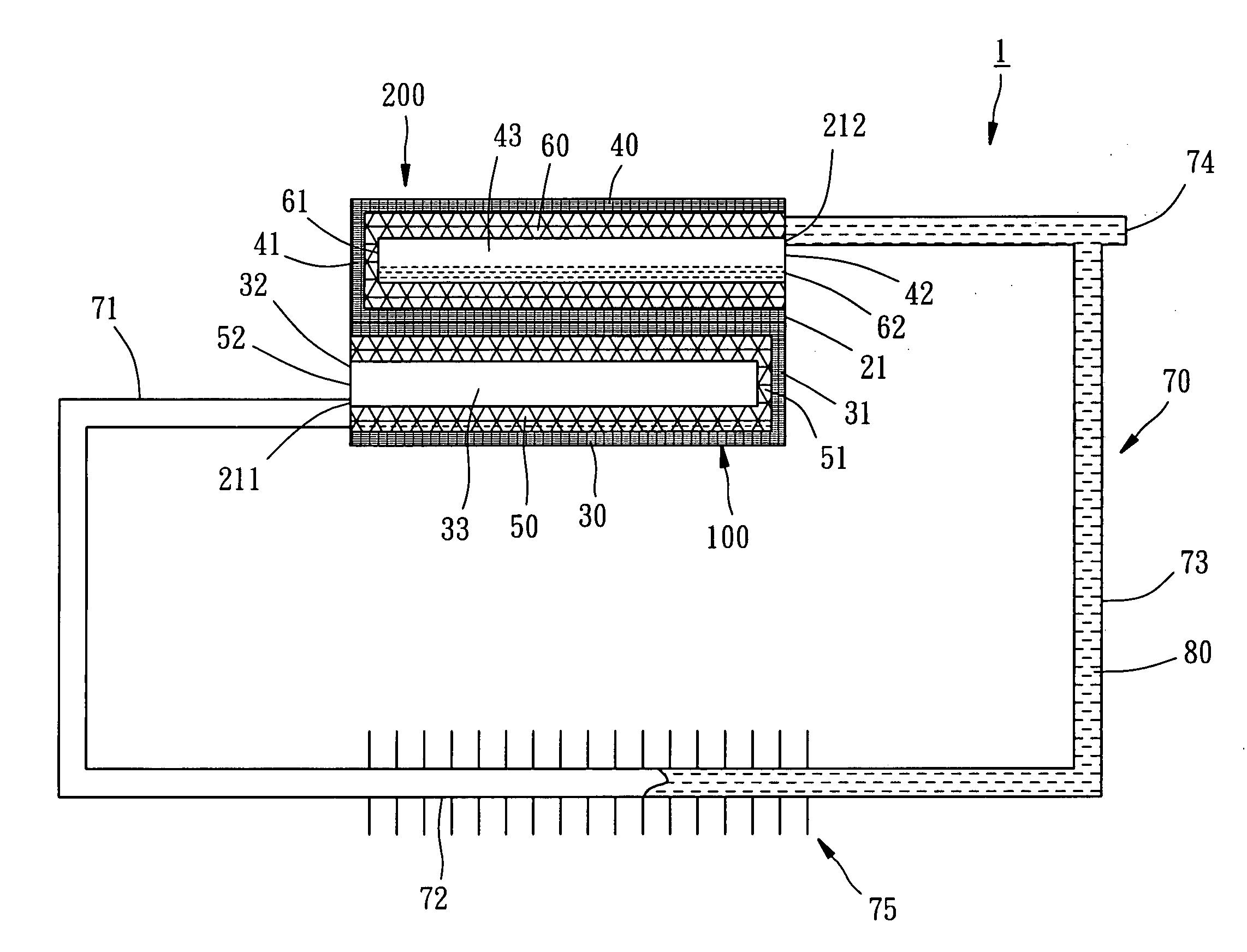
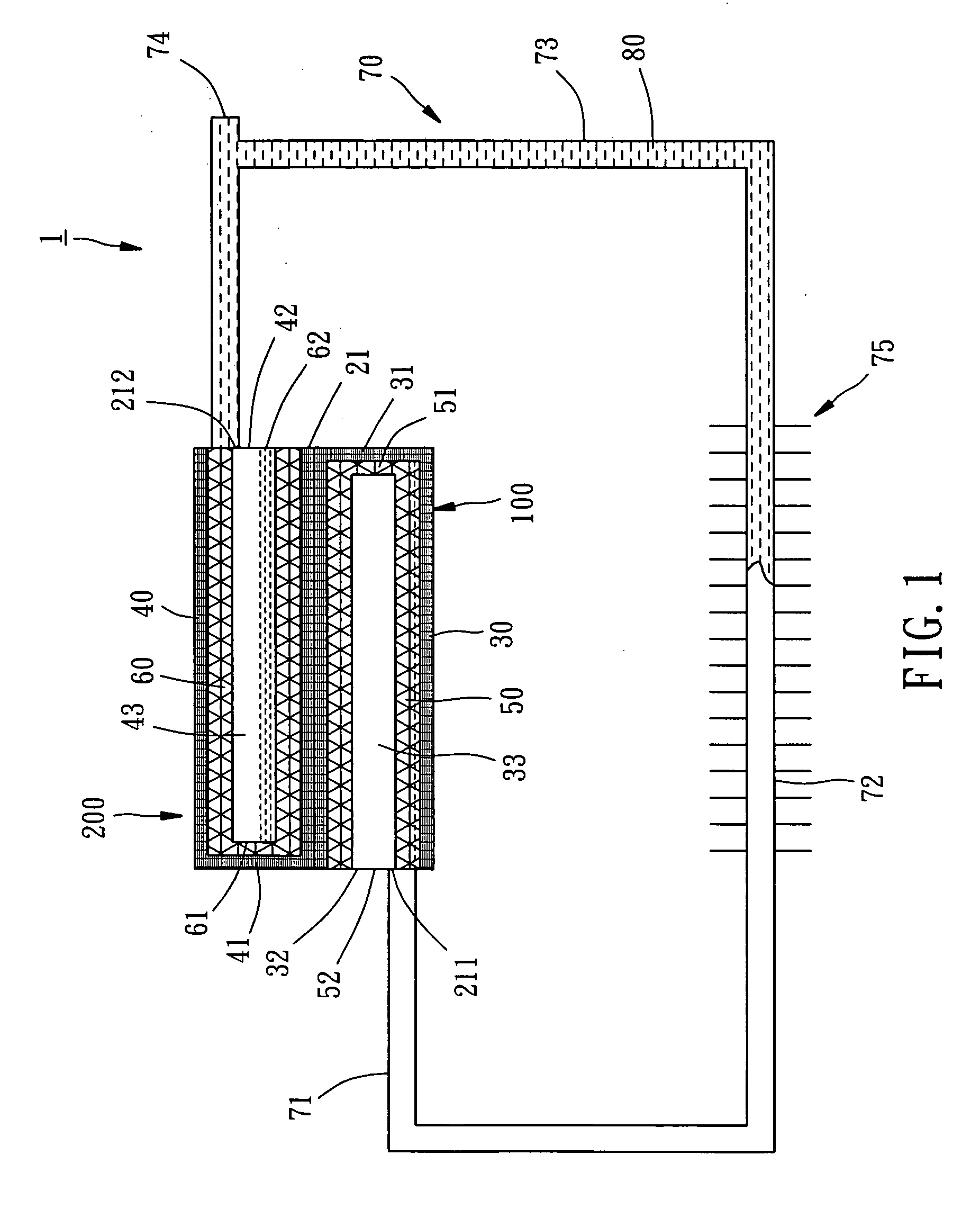
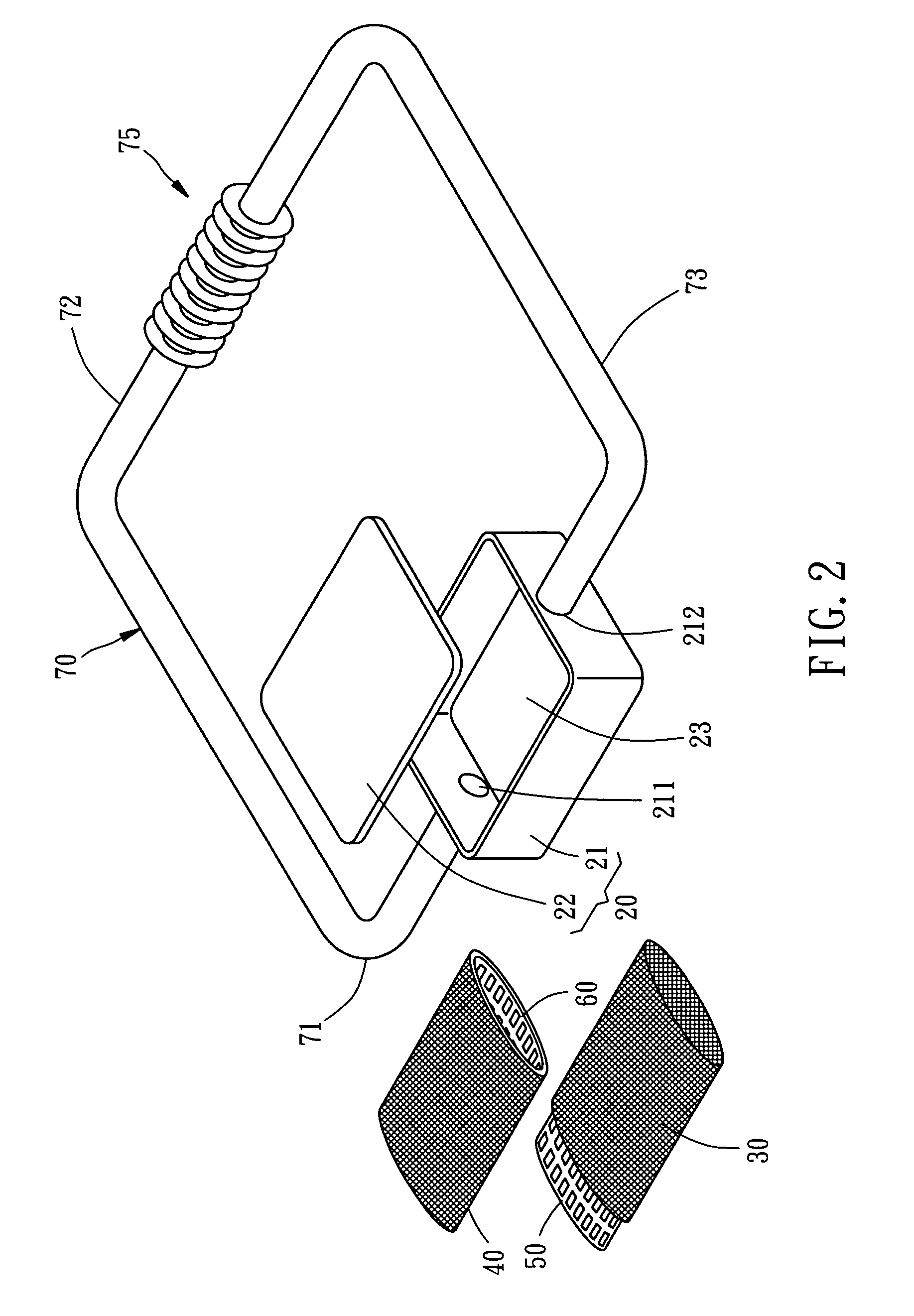
[0014]Referring to FIGS. 1-4, a flat LHP 1 constructed according to a preferred embodiment of the present invention is composed of a container 20, a first capillary core 30, a second capillary core 40, a first support member 50, a second support member 60, a circulatory pipeline 70, and a working fluid 80.

[0015]The container 20 includes a case 21 and a cover 22. A chamber 23 is formed inside the container 20 and between the case 21 and the cover 22. The case 21 has two openings, which are a vapor outlet 211 and a liquid inlet 212 respectively. The distance between a center of the vapor outlet 211 and a bottom side of the base 21 is smaller than the distance between a center of the liquid inlet 212 and the bottom side of the case 21. The vapor outlet 211 and the liquid inlet 212 are mounted to a left side and a right side of the base 21.

[0016]Each of the first and second capillary cores 30 and 40 is structurally capillary and thin sleeve-shaped, having a close end 31(41) at one end t...


PUM


Abstract

A flat loop heat pipe is formed of a first capillary core, a second capillary core, a first support member, and a second support member. The first capillary core and the first support member constitute an evaporation room. The second capillary core and the second support member constitute a compensation room. In light of this structure, it is not difficult to activate circulation of thermal dissipation under low-watt heat source and the first capillary core can avoid dry-out phenomenon.

Description

BACKGROUND OF THE INVENTION[0001]1. Field of the Invention[0002]The present invention relates generally to heat-dissipating technology, and more particularly, to a flat loop heat pipe.[0003]2. Description of the Related Art[0004]A conventional loop heat pipe (LHP) is an effective heat-dissipating device and generally composed of an evaporator, a vapor line, a condenser, and a liquid line, all of which are connected and communicated with one another to become a loop containing a working fluid. The evaporator includes a capillary structure connected with a heat source. A compensation chamber is provided between the liquid line and the capillary structure. When the evaporator absorbs the heat from the heat source, the working fluid inside the LHP also absorbs the heat from the heat source to produce vapors. The vapors flow through a pipeline from the evaporator toward condenser chamber and then give out the heat at the condenser to be condensed and converted into liquid, and then the l...

Claims


Application Information

Patent Timeline
IPC IPC(8): F28D15/02
CPCF28D15/0266F28D15/046F28F2225/00
Inventor CHIN, CHI-TE
Owner CHIN CHI TE
Why Eureka
Try Eureka