Rotary position sensing apparatus

a technology of rotary position and sensing apparatus, which is applied in the direction of mechanically converting the output of the sensor, instruments, transportation and packaging, etc., can solve the problems of introducing accuracy error and hysteresis, damage to optical sensors, and generally short life of potentiometers, so as to prevent rotational movement of the nut

Inactive Publication Date: 2010-07-01
HONEYWELL INT INC
View PDF12 Cites 77 Cited by
  • Summary
  • Abstract
  • Description
  • Claims
  • Application Information

AI Technical Summary

Benefits of technology

[0008]Embodiments of the present invention describe rotary position sensing apparatus that are based on the lead screw principle. An angular position sensor for determining angular position comprises a shaft having a threaded portion, and a structure for engaging an external application. The external application involves rotation of a rotatable member. When the external application is engaged, the rotation of the rotatable member rotates the shaft. The shaft includes a first permanent magnet. The first permanent magnet is generally aligned to have its poles oriented along an axial direction of the shaft. A nut is threaded on the threaded portion. The nut is formed from a first magnetic permeable material or comprises a second permanent magnet. At least one constraint, such as a guide bar, is coupled to the nut for preventing rotational movement of the nut while allowing linear motion of the nut.

Problems solved by technology

However, potentiometers generally have very short lives because of sliding contacts which tend to wear out after prolonged use.
Optical encoding has several disadvantages including reliability problems due to dust or mud which can easily damage the optical sensor.
These methods generally require a step-down gear mechanism for angle requirements more than 360° which will affect the resolution of sensor also introduce accuracy error and hysteresis due to backlash and wear and tear.
However, a disadvantage in such a configuration is the voltage variation per degree which results in such arrangements lacking in the accuracy as the angle to be sensed becomes relatively large.
Hydraulic power steering can sap a car's performance creating parasitic power loss and driving down fuel economy as much as five (5) percent.
However, for this kind of application it is necessary that the sensors are fault tolerant and have memory which will work even though no electrical power is there and steering column is moving.
Electromagnets will generally be more difficult in typical applications as there are moving parts, and power needs to be supplied to the electromagnet.

Method used


Image

  • Rotary position sensing apparatus
  • Rotary position sensing apparatus
  • Rotary position sensing apparatus

Examples


example

[0054]The following non-limiting Example serves to illustrate selected embodiments of the invention. It will be appreciated that variations in proportions and alternatives in elements of the components shown will be apparent to those skilled in the art and are within the scope of embodiments of the present invention.

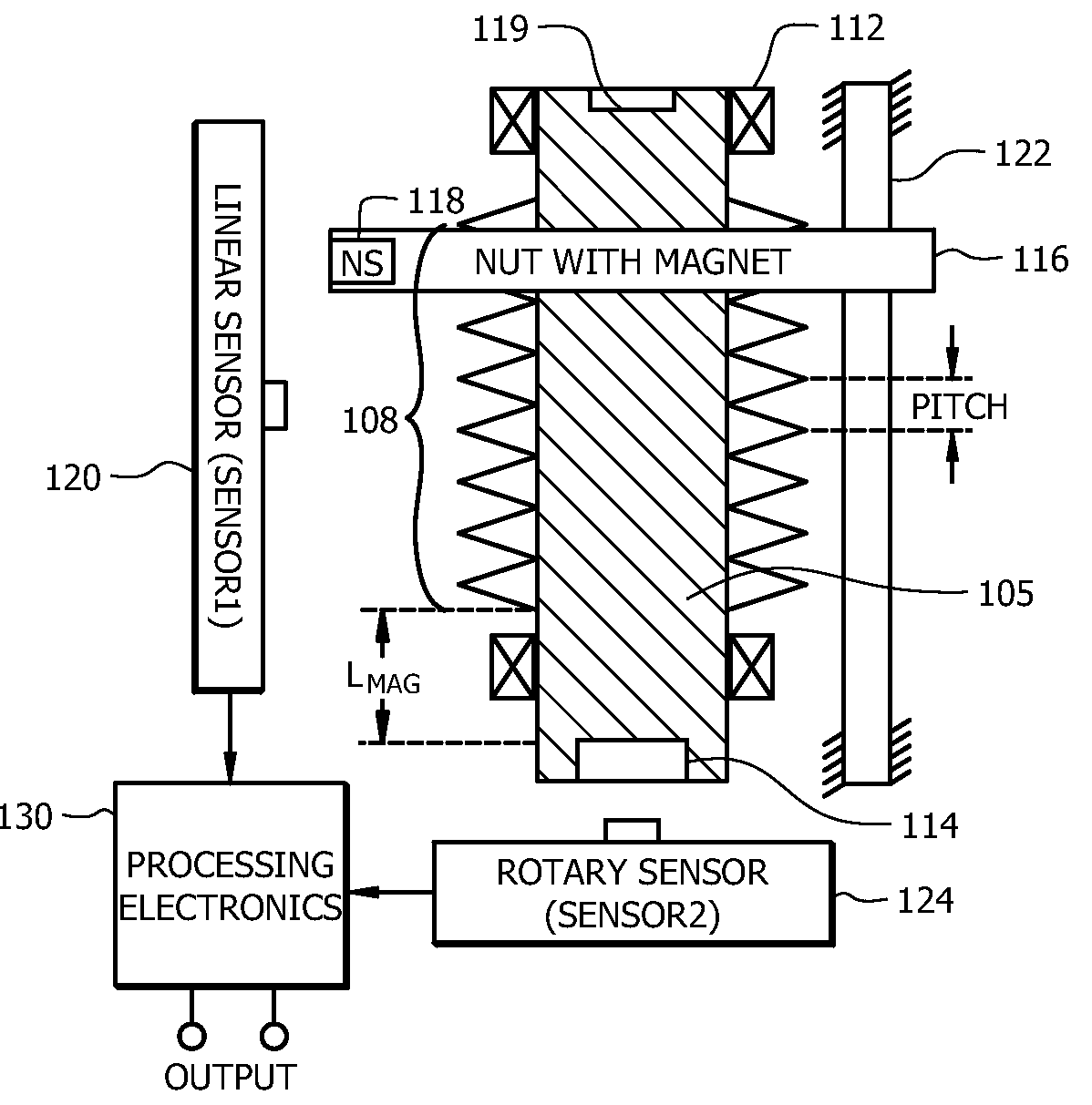
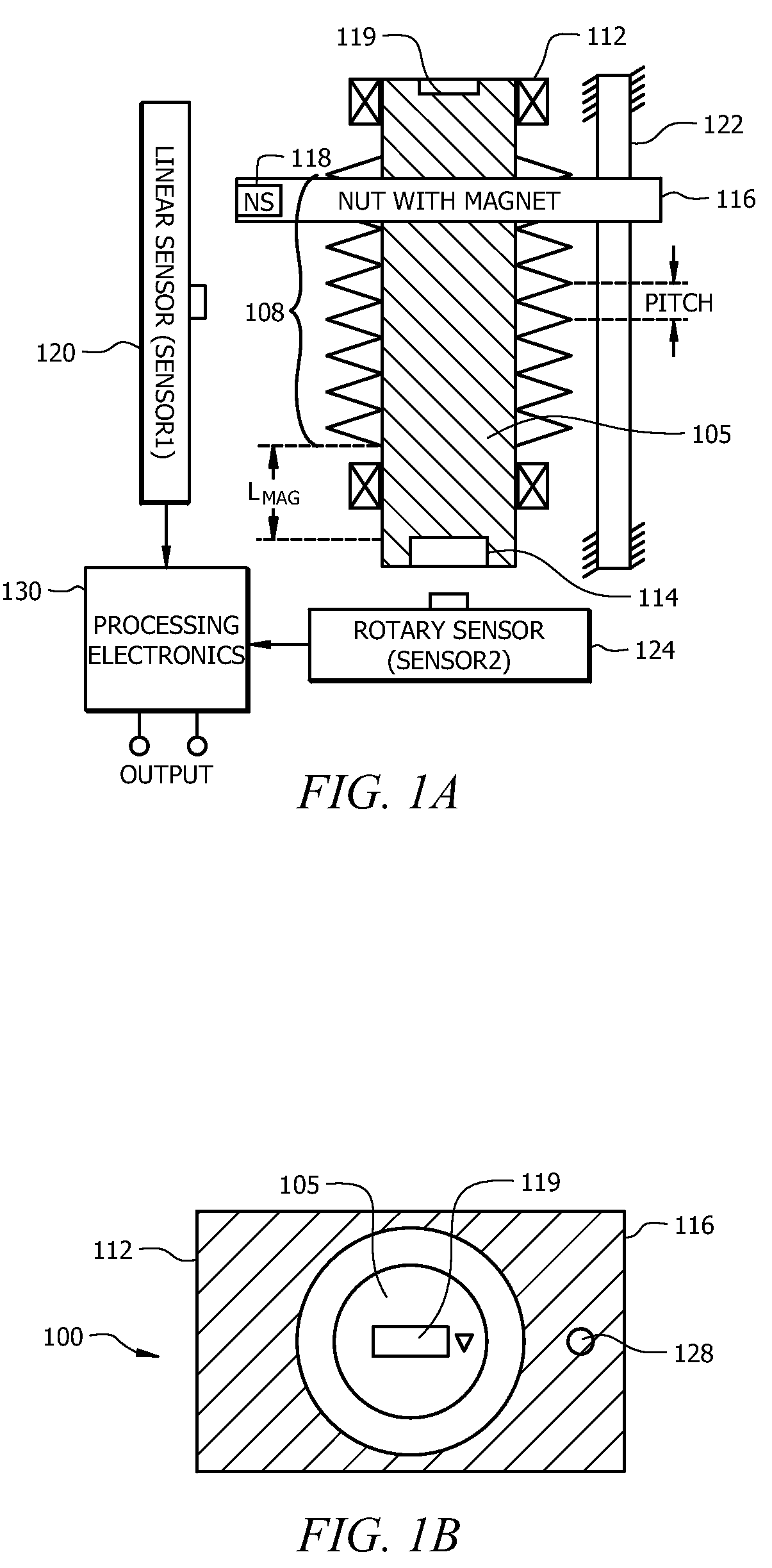
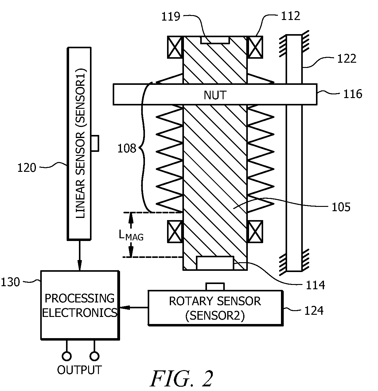
[0055]Assume the pitch of the threaded portion 108 (e.g. screw)=1 mm. Accordingly, the nut 116 will move 1 mm up or down depending on the direction of rotation of shaft 105 per rotation of shaft 105. Assume the reading from first magnetic sensor 120 is calculated to correspond to 1.5 mm. This means nut 116 is in the second turn. Assume the reading from the second magnetic sensor 124=180°. The actual angle output from electronics processing circuitry 130 would then equal the fractional turn reading from second magnetic sensor 124 added to 360×(the integer turn count from first magnetic sensor 120−1)=180+360*(2−1)=540°.


PUM


Abstract

An angular position sensor (100) for determining angular position includes a shaft (105) having a threaded portion (108), and a structure for engaging an external application (119). The shaft (105) includes a first permanent magnet (114). A nut (116) is threaded on the threaded portion (108). The nut (116) is formed from a first magnetic permeable material or includes a second permanent magnet (118). At least one constraint (122) is coupled to the nut (116) for preventing rotational movement of the nut (116) while allowing linear motion of the nut (116). A first magnetic sensor (120) is positioned along a length of the threaded portion (108) of the nut (116) for measuring a linear position of the nut (116). A second magnetic sensor (124) is provided for measuring an angular position of the shaft (105). Signal processing circuitry (130) is coupled to receive outputs from both the first magnetic sensor (120) and second magnetic sensor (124) for calculating a parameter relating to an angular position of the rotatable member.

Description

FIELD OF THE INVENTION[0001]The present invention relates to rotary position sensing apparatus, and in particular to rotary position sensing apparatus that can sense angles in excess of 360 degrees.BACKGROUND[0002]The application of electronics in automobile mechanical systems for better performance is increasing the percentage of electronics parts in an automobile system day by day. Demand for accurate, reliable and non-contact sensors which are essential parts of electronic control is also increasing. For example, rotary position sensors are sensors used for sensing the rotational position of the shafts, axles or columns such as steering columns. The output from rotary position sensors comprises rotation position. Rotation position refers to the orientation of the shaft and the number of turns the shaft is rotated from the beginning of the reference position.[0003]Rotary position sensors are used as steering wheel sensors. A steering wheel sensor provides the value of the angular ...

Claims


Application Information

Patent Timeline
Patent Type & Authority Applications(United States)
IPC IPC(8): B62D5/04G06F15/00
CPCB62D15/0215B62D15/0245G01D5/145G01D2205/22G01D2205/26
Inventor PATIL, SWAPNIL GOPALRAMAMURTHY, GAUTHAMIBRAHIM, NURUL HASANRAJ, AZHAGAR
Owner HONEYWELL INT INC
Why Eureka
Try Eureka